In this post, I would like to bring you some knowledge about the geolocation of drawing in the AutoCAD LT version. At some point, you can find here some repeatable stuff showing you the relevant steps for making this task successful. However, I wouldn’t have decided to post this article if I had seen the explanation of how to make successful geolocation for large drawings, covering even whole towns or small administrative units! This is the case, which might occur in some of your advanced AutoCAD works. There are a lot of tutorials on the web explaining correctly how to geolocate our AutoCAD work successfully, but usually, they deal with small drawings, being commonly deprived of any discrepancies becoming visible in the case of bigger drawings.
The drawing used for the purpose of this article counts almost 8km in length (Pic. 1), so some geolocation inaccuracies are inevitable for an area such as this.

1. Our drawing can be geolocated easily by using the Main bar -> Insert -> Set Location -> From map or From file. If we choose the option From Map, we need to find the address of our work and drop the marker there. In fact, it can be done automatically, but we can drag it manually later or move it to another place by the mouse right-clicking (Pic. 2).

The Set Location option can be also launched by typing GEOGRAPHICLOCATION in the command bar at the bottom. Everything looks simple, although because we are dealing with seriously big and extended drawings, some rules must be applied here. In order to reduce further inaccuracies, we should drop our marker more or less in the middle of our drawing (Pic. 3) by choosing some easily recognizable spot for us (i.e. some road junction).

If you are unsure about this step, you can try to provide the geolocation from the file by choosing the option:
Main bar -> Insert -> Set Location -> From file.
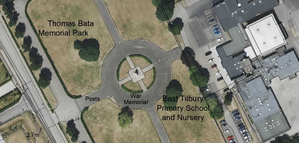
Your file will be just a simple placemark from Google Earth with the coordinates defined roughly in the place you want to reference against some characteristical spot on your CAD drawing (Pic. 4).

The Geolocation from files in AutoCAD can be set just from .kml or .kmz files, whereas predominantly I believe, only .kml will be in use. The best option for it is using Google Earth or a similar application, which provides placemarks with extensions such as this (Pic. 5, 6).


For proof, that everything works fine let’s see the comparison below (Pic. 7). The AutoCAD LT reads accurately the coordinate data stored in the .kml placemark provided.

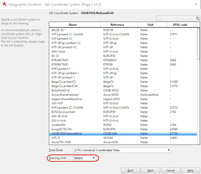
When we set our address correctly, we can click the “Next” button and jump to the list of coordinate systems. Another step of the geolocation is defining the coordinate system appropriate for our drawing (Pic. 8). Make sure, that your Drawing Unit is defined in Meters!
2. Define the point of your location on your drawing. The best option is clicking roughly in the place, which firmly corresponds to the map marker discussed earlier. Next, provide the north direction. It can be done in two ways – by specifying the angle or defining two points, where the first point marks the beginning and the second point is the end of the line defining the north direction. When these 2 requirements are completed, the map canvas should appear in our AutoCAD drawing (Pic. 9).

And basically, our job should be completed. However because our drawing is fairly big, we should double-check all the corners. Since your layer is not visible properly, you can change its color in the Main toolbar -> Layers -> Layer Properties panel.
At first glance, we can see, that as far as we are going from the reference point, our drawing is shifted against the map canvas (Pic. 10).

This kind of inaccuracy is driven by a mismatch between the north arrow direction defined by us and provided by the chosen coordinate system (Pic. 11).

We can use the following option: Main bar -> Geolocation -> Reorient Marker, where we can replicate some steps.
3. By the way, we can fix the shift caused by the wrong placement of our geolocation point. Before we use the Reorient Marker option, we can make the relevant measurements by opening: the Main bar -> Home -> Utilities -> Measure -> Distance.
Since our distance is known, we can draw some auxiliary line or polyline in order to place our georeference point correctly thereafter (Pic. 12).

4. Now, we can go to the Main bar -> Geolocation -> Reorient marker and provide the correct data. Firstly for the geolocation point, as per our auxiliary line provided, and secondly by fixing the north arrow direction (Pic. 13).

There are effectively 3 ways of adjusting the north direction:
– by simply marking the line from the geolocation point. The endpoint of this line (mouse click) defines the north angle,
– by marking the first and second points of the line, where the first point might fall independently from the geolocation point,
– by providing the angle value in the command box (Pic. 14).

Let’s focus on the last option. Once the Reorient marker is used, and a user approaches the moment of Specifying the north direction, he can see some value in the brackets next to it. This value is the recent north-direction angle, which has been applied. It’s a very useful element, which might help us a lot with adjusting the drawing placement against the map. After the colon on the right, we can type our own angle value and hit enter. The map will suddenly rotate. The typed value can be even in decimals, but later the number will be rounded to the total value in the brackets.
Anyhow, after these geolocation alterations, our drawing should fall correctly against the map canvas provided (Pic. 15).

Removing any geolocation inaccuracies for large drawings in AutoCAD LT is a quite simple thing, but requires a bit of something like a trial-and-error method. Using the Reorient Marker option just once may not give you a satisfactory result. You need to repeat it then until your drawing will match the map canvas (or satellite imagery) provided.
Mariusz Krukar
References:
- Benton B. C., Omura G., 2021, Mastering AutoCAD 2021 and AutoCAD LT 2021, John Wiley & Sons Inc., Indianopolis, Indiana
Links:
- https://mgfx.co.za/blog/building-architectural-design/using-the-set-location-tool-in-autocad-to-add-a-terrain-image-to-your-drawing/
- Help.autodesk.com: About setting geographic location
- https://www.cad-elearning.com/autocad/what-is-geolocation-in-autocad/
- Knowledge.autodesk.com: GEOGRAPHICLOCATION command
- Knowledge.autodesk.com: Setting the geographic location
- https://graitec.com/uk/blog/autocad-autocad-lt-free-aerial-mapping/
- Knowledge.autodesk.com: To set geographic location from the map
Forums:
- https://forums.autodesk.com/t5/autocad-forum/geolocation-map-is-not-matching-with-drawing/td-p/7816245
- https://www.cadtutor.net/forum/topic/68749-map-doesnt-match-georeferenced-dwg/
- https://www.cadforum.cz/en/the-geolocation-livemap-in-autocad-2014-is-off-scale-tip9202
- Knowledge.autodesk.com: GEOGRAPHICLOCATION-live-maps-don-t-display-within-AutoCAD-2021-or-newer-versions.html
Youtube: