
After browsing the internet and trying my own approaches finally, I can come out with a nice method, that allows you to pass the attribute table data from your QGIS project to AutoCAD LT. Basically, the QGIS project can export to the AutoCAD environment easily. It’s just going to the Project -> Import/Export -> Export Project to DXF, where optionally we can pick up some important layers for us. I will jump to this section later, as I need to discuss some important stuff before.
Altrnatively, you can save (export) our layer in the .dxf format, but personally, I would advise the first option mentioned. There is also another way reserved for more advanced levels, namely the GDAL (ogr2ogr) option.
If you have the full version of AutoCAD, there is no problem with transferring your QGIS project with attribute tables. It can be done quickly by the MAPIMPORT command, which converts the shapefile geometry to AutoCAD geometry quickly along with attribute content, or MAPCONNECT command, which can do similar.
The problem begins when instead of the full version of AutoCAD you have AutoCAD LT. In this case, there’s no option for exporting the QGIS files with the attribute table! This is what this article is for. I would like to explain some ways, which potentially could be applied when we really need to have some attribute table data in our AutoCAD LT project.
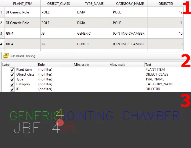
Our QGIS data looks as follows (Pic. 1), where 2 layers will be considered – the line and point layer.
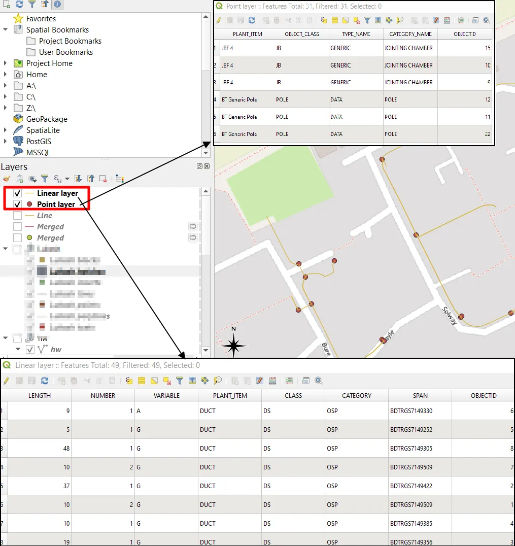
The most important is to take a look at the column names in our attribute table.
Our very first step is the label definition for these 2 layers.
These labels can be defined in 2 ways. We can set the proper formula with concatenation, which will bind all the important attribute data together in the label. We can also define the rule-based labeling for some attribute columns and place them on other sides of our object.
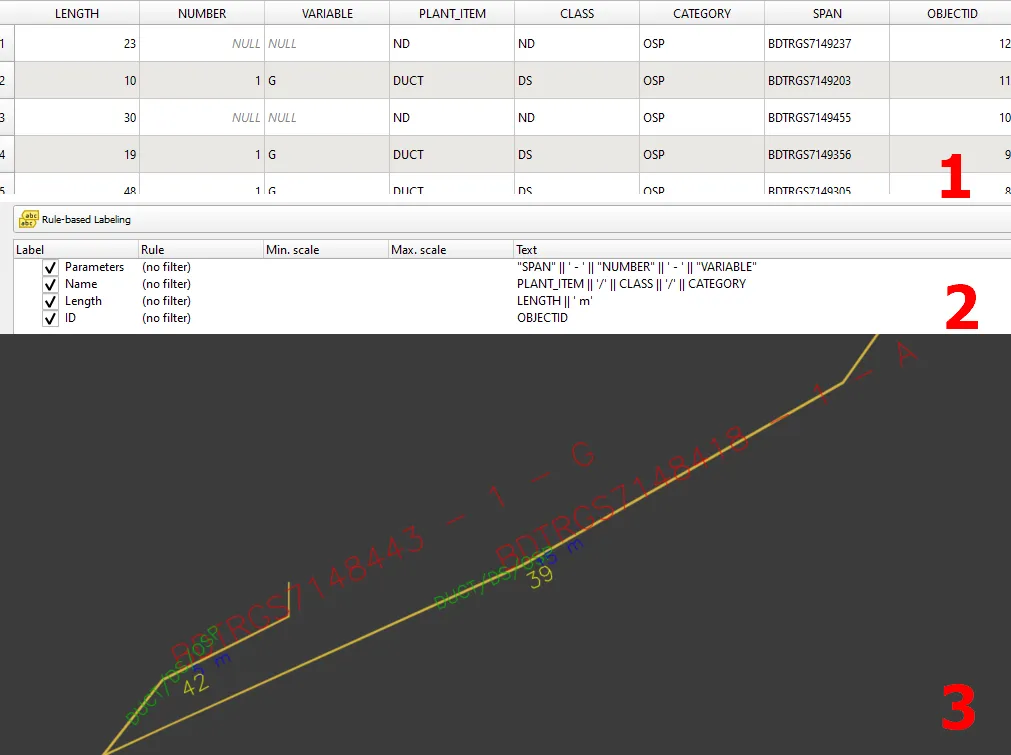
Let’s see the first method. By watching our linear layer below, we could prepare the following formula:
‘ID ‘ || “OBJECTID” || ‘ – ‘ || “SPAN” || ‘ – ‘ || “CATEGORY” || ‘ – ‘ || “NUMBER” || ‘ – ‘ || “VARIABLE” || ‘: ‘ || “LENGTH” || ‘ m’
which essentially includes most of the attribute table columns (data) presented above (Pic. 1). It’s just a pure concatenation done here with some string injections between, although it’s worth knowing, that any kind of expression can be passed here as long as correct to the circumstances provided. Next, we should seriously consider the appearance of our text. Because our goal is to show it nicely in AutoCAD LT, we need to use some bright-colored font and make it slightly smaller when necessary (Pic. 2).
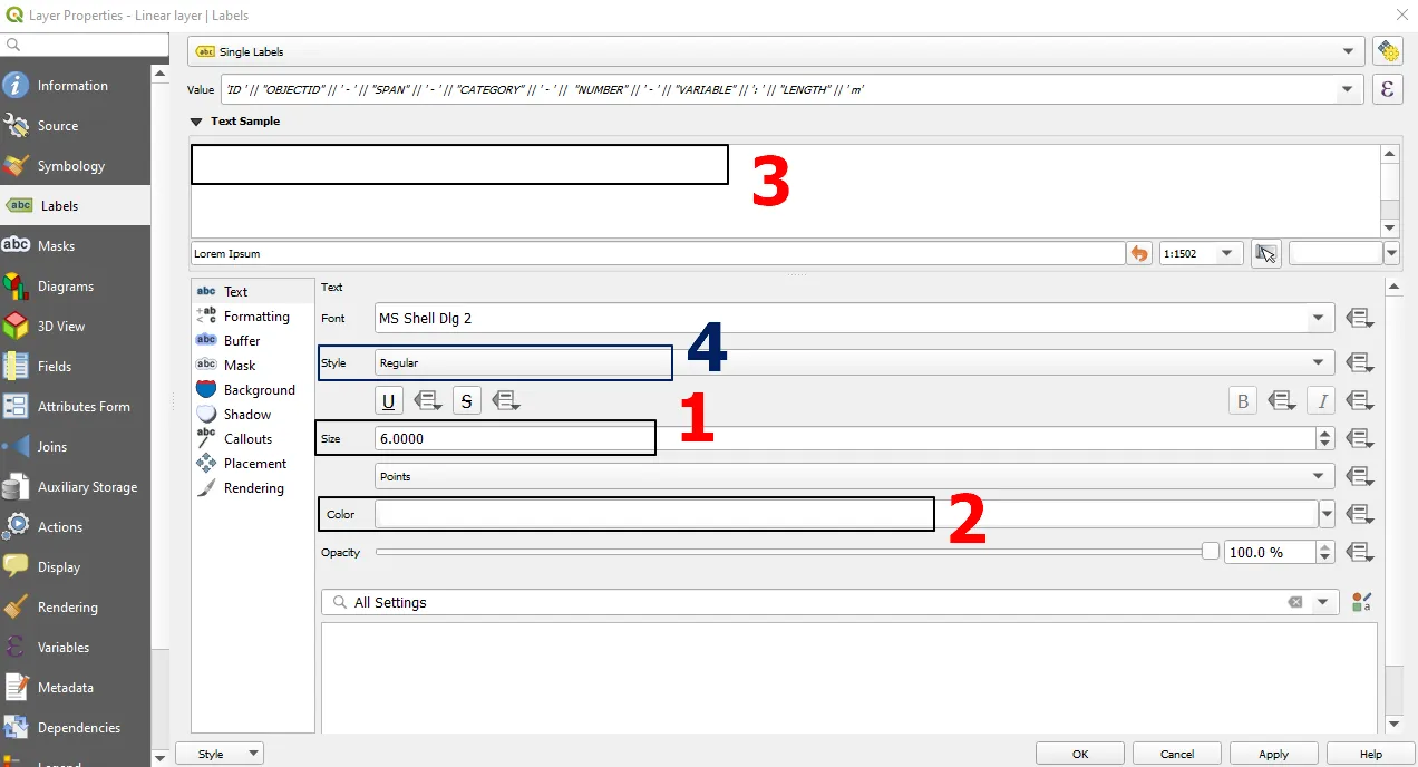
Our output situation should look pretty much like the above (Pic. 2). The font has been decreased slightly from the default value and its color was changed to white making it invisible on the white “Text Sample” box background. The formula prepared above is now visible in the Value box. An analog thing can be now done for the second layer, but I will use just one value for the time being. In this case, my formula will look like this:
CASE when
"OBJECT_CLASS" = 'JB' THEN
"PLANT_ITEM"
Else
''
End
in order to exclude some labels from the display.
When your matter with labels is sorted, you can optionally switch off the symbology, if you wish to have just the data only.
The most important step now is to export our work to the AutoCAD DXF file, which can be done in the following way:
Project -> Import/Export -> Export project to DXF
and choose the right options in the dialog box opened (Pic. 3).
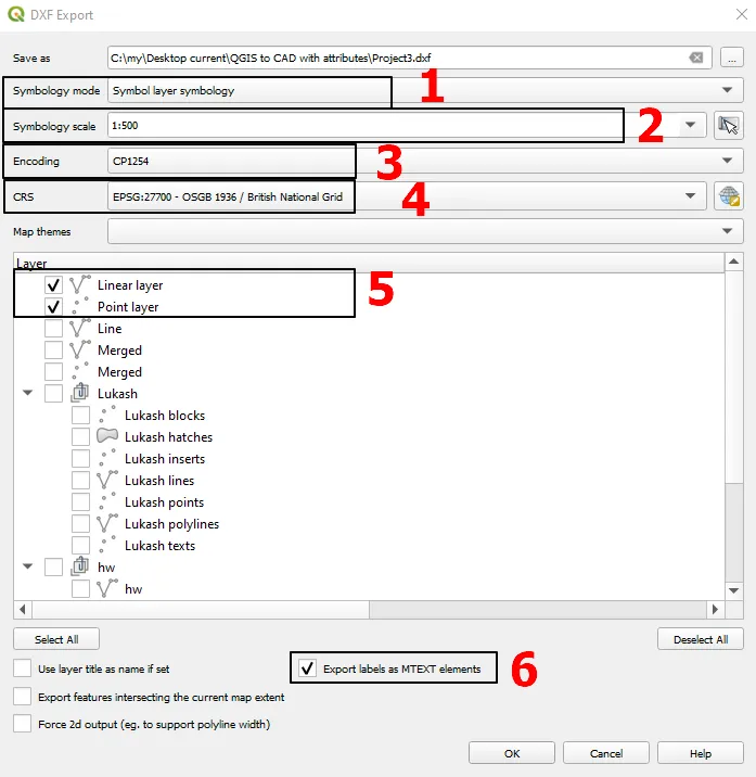
First of all, the Symbology mode is the most important option here! We have 3 selections, and for us, it can be the Symbol layer symbology. It allows for more complete reproduction of complex symbology. In fact, our case doesn’t represent this type of symbology, so the second one – Feature Symbology could be still good.
Symbology scale is another option, as default the 1:1000 is recommended, although it depends on your project, especially the print scale on your viewport in AutoCAD, therefore is hard to define some uniform criteria here. As a matter of fact, the scale strictly corresponds to the font size defined in our labels. When you decide to decrease your font number to 2 or 3px instead of 6, then the scale 1:1000 should bring a similar result to 1:500 for the font size 6px.
Encoding is set to CP1252 (Windows-1252) as default and it works fine with special characters typical for languages other than English, so it’s good to leave it as it is. When you need to figure out more about the encoding types offered by this option, you can read about some differences between them i.e. here.
CRS – it’s another important option. I bet, that you will need this .dxf file to be eventually combined with your general AutoCAD LT project by using the PASTEORIG command. To make it work properly, the CRS system must correspond to the one used in our AutoCAD LT.
Finally, we are reaching the essence of our project – the Layer box, which shows all the layers included in our QGIS project. For the current purpose, we need just 2, so you can unselect the other ones. You have a free choice here, there is no necessity of exporting all the layers. Even one layer can constitute our QGIS project.
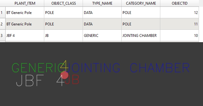
The last option to be selected is to Export labels as MTEXT elements. This particular selection includes 2 ways of exporting our labels – as MTEXT and as TEXT. What is the difference between them? In the AutoCAD environment, MTEXT means simply multiline text, which gives more options on how the text object can appear in our drawing. TEXT is not flexible that much, although it takes less memory, so it’s faster in rendering the drawing. From our point of view, it’s good to show the difference from the QGIS’s side, which is best presented in the image below (Pic. 4).
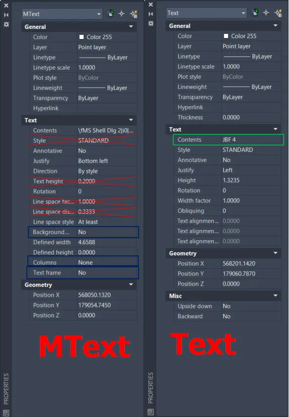
It’s not everything! As you can see, there are some options simply ruled out from this image. They apply just for the MTEXT type and seem to not work properly in AutoCAD LT. The most important for us undeniably is the Style, which could be applied in bulk by Right-click -> Select Similar -> Right-click on the item -> Properties. In the case of MTEXT, it simply doesn’t work! You need to double-click on the text and then change it. As it is worse, you have to do it one by one! Even the REGENALL command won’t be helpful here!
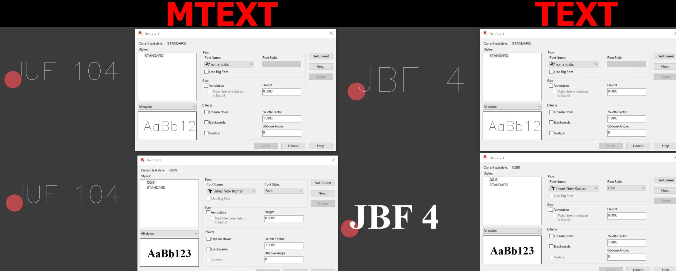
Everything depends on the final visual output you want to have. If you don’t want to have your font emboldened, then MTEXT might be better for you, because there you have an option for defining for example the background (Pic. 6).

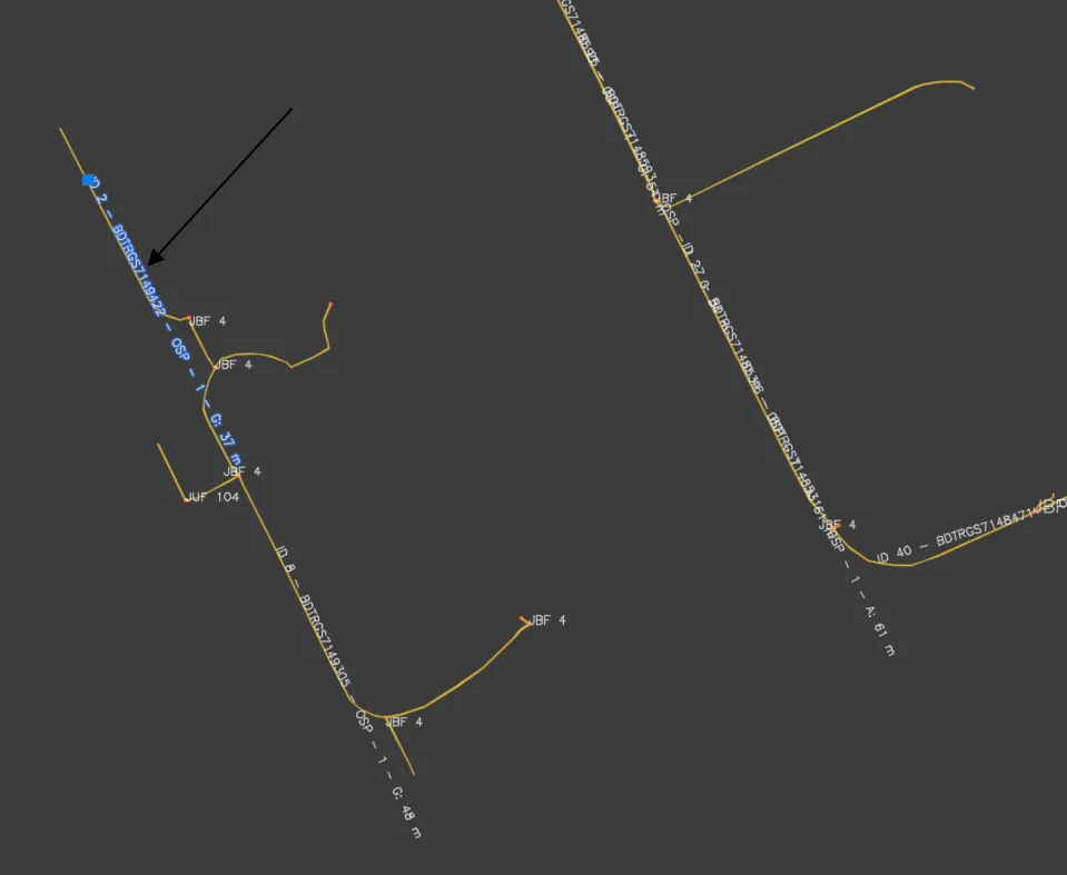
Finally, after opening the .dxf file in AutoCAD you should have the attribute data parsed in labels (Pic. 7). You are in a good situation, because despite just one layer binding up both objects and their labels, each element acts like individual body, therefore you can move it or rotate as you wish. Don’t be disappointed when you get your labels messy, because everything can be fixed manually, but quickly now.
Now is the time for the second way of transferring the attribute data from QGIS to AutoCAD LT. This time I am going to use the rule-based labeling option In a case such as this, we can effectively define the separate rule for every single attribute table column. The difference between them will be color and placement against the mother object (Pic. 8).
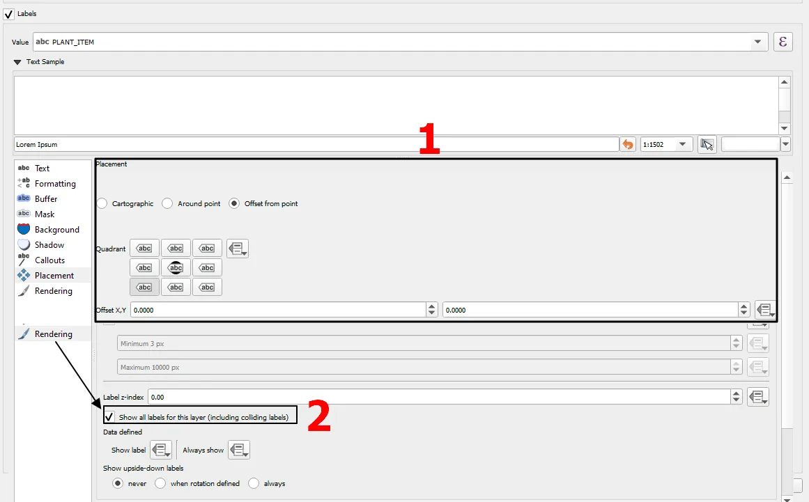
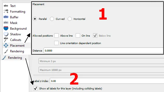
Assuming, that you’ve done everything in the Text section, now there are things to set up in the Placement section. The default placement is set as Around point, but it has to be changed to Offset from the point. Next, you can specify the Quadrant, in which the given label will appear. Optionally you can offset it additionally by using X and Y parameters. Remember, that they are based on the Cartesian coordinate system, which starts roughly at the quadrant defined. There is another option to set active, namely the Show labels for this layer (including colliding labels). It will prevent us from the unforeseen disappearance of some labels. All the steps must be done for every single label defined! Your output for the point layer could look like this (Pic. 9).
Obviously, the coloration, size, and placement can be also altered in AutoCAD LT. Treat the image above as an example.
In the case of a linear layer, we can still use the expression including some concatenations, but they could be shorter this time, as a piece of our formula can go underneath or above the line (Pic. 10). Unfortunately breaking the line doesn’t come through.
Finally, our view in AutoCAD LT should look as you can see below (Pic. 11).
When we have too many labels packed in one expression, the font size settings, unfortunately, might not come through, although they’re changeable easily later in AutoCAD LT when the TEXT type of label is applied.
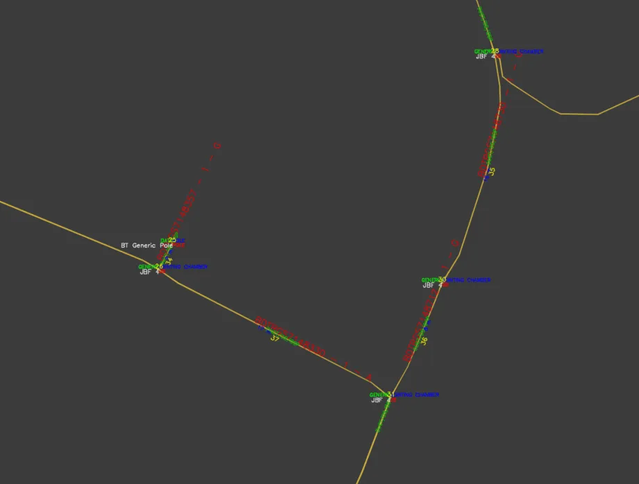
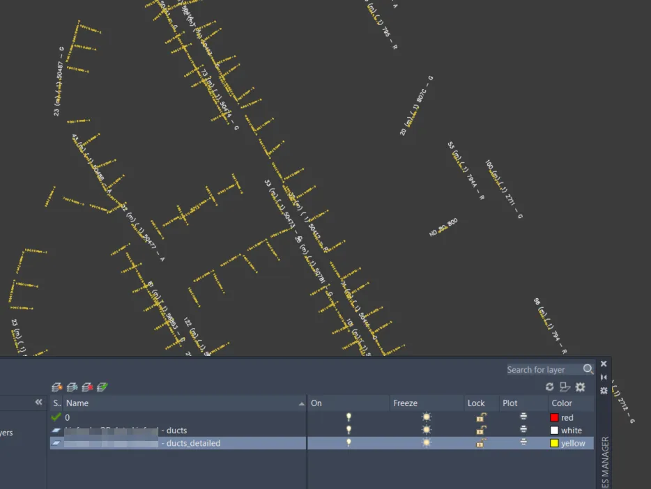
Our final work in AutoCAD LT for both layers should look like the one below (Pic. 12).
There are important things to mention before you start doing work such as this. Firstly – make sure, that you are always exporting your QGIS project to DXF via Project -> Import/Export -> Export Project to DXF… Exporting your layer as DXF via Export -> Save Features As… is not the same! Despite setting for DXF export, which looks the same, your labels won’t be generated.
Secondly – bear in mind, that setting a bigger font size for your labels (or providing too big Symbology Scale) will result in missing some labels, especially the longer ones. The cavity might reach even 20% of results in total, but it’s just an assumption based on my own project, Your situation might be different. The solution for it is to create two separate layers, where the first one will correspond to your AutoCAD LT project requirements. The second one will act as the auxiliary layer featuring considerably smaller text size at the export stage in order to replicate 100% of labels in AutoCAD LT. Remember, that when you import the same layer twice, AutoCAD LT won’t recognize them, binding everything in one layer finally. Before you import the second layer, change its name slightly (Pic. 13). This layer will be removable easily later in your AutoCAD LT project.
This is the most reasonable method of passing some attribute data from QGIS to the CAD drawing in the case when you are working just on the Lite version.
Mariusz Krukar
Links:
- https://www.qgis.ch/en/projects/dxf-export
- https://docs.qgis.org/3.16/en/docs/user_manual/managing_data_source/create_layers.html#create-dxf-files
- https://gis4design.wordpress.com/2015/10/16/qgis-exporting-as-dxf/
- Support.esri.com: How To: Export to AutoCAD DWG or DXF format and maintain attributes
- Desktop.arcgis.com: Exporting attribute values to AutoCAD block attributes
- https://gisforthought.com/gis-to-cad-using-ogr2ogr-part-1-shp-to-dxf-with-contour-data/
- Comparing Characters in Windows-1252, ISO-8859-1, ISO-8859-15
- Knowledge.autodesk.com: REGENALL (Command)
Forums:
- Github: [DXF Export] attributes not exported
- https://gis.stackexchange.com/questions/24806/exporting-to-dxf-file-from-qgis
- https://gis.stackexchange.com/questions/192927/batch-export-multiple-layers-to-dxf.
- Forums.autodesk.com: How to transfer shapefile attributes from GIS into AutoCAD Civil3D 2018
- https://gis.stackexchange.com/questions/16250/shapefile-attributes-to-autocad-annotation
- Forums.autodesk.com: import shapefile to cad with attribute table Erorr
- Help.locusgis.com: SHP to DWG vith atributes (Czech)
- Forums.autodesk.com: Linking Attribute Data to Tables
- reddit.com/r/AutoCAD/comments/9giw3d/export_csv_file_to_dxf_with_value/
- Forums.autodesk.com: IMPORTING EXCEL POINTS INTO LT?
- https://gis.stackexchange.com/questions/380309/how-to-export-labels-from-qgis-to-cad
- Mail-archive.com: [Qgis-user] Labelin in export to DXF
- https://stackoverflow.com/questions/19109899/what-is-the-exact-difference-between-windows-12521-3-4-and-iso-8859-1
- Forums.autodesk.com: what is the advantage of TEXT over MTEXT
My questions:
- https://gis.stackexchange.com/questions/440628/qgis-file-exported-as-autocad-dxf-not-visible-on-the-map-and-loosing-attribute-t
- https://engineering.stackexchange.com/questions/53314/autocad-how-to-change-font-style-for-multiple-items-at-once?noredirect=1#comment100888_53314
- https://gis.stackexchange.com/questions/374347/qgis-3x-label-is-gone-when-zoom-out
Wiki:
Youtube: