PDF drawing – the fastest georeference with AutoCAD LT
PDF documents are very popular. They can include various content from text through simple drawings to detailed maps of some areas. Storing drawings, plans, or maps in PDF files is very convenient because this format is platform-independent. It means, that any kind of map, plan, or sketch can be viewed, shared, and printed in various operating systems. Moreover, the file size is compressed, which makes it easy to transfer, open and download. This is why the PDF format is the best for business. We can find 2 basic types of PDF files – the raster and vector ones. Raster PDF is just a scanned document, whereas the vector content usually includes drawings or maps broken down into separate and extractable layers. Another type is the GeoPDF, which is the PDF including georeferenced data.
This article is about the exercise, which requires input of the PDF map to our AutoCAD LT project as quickly as possible. For this reason, georeference is required, which is explained later in this text.
Our .pdf file includes the development plan, which must be placed in the AutoCAD LT project. The file type is a vector, although the document itself isn’t scaled properly (Pic. 1).
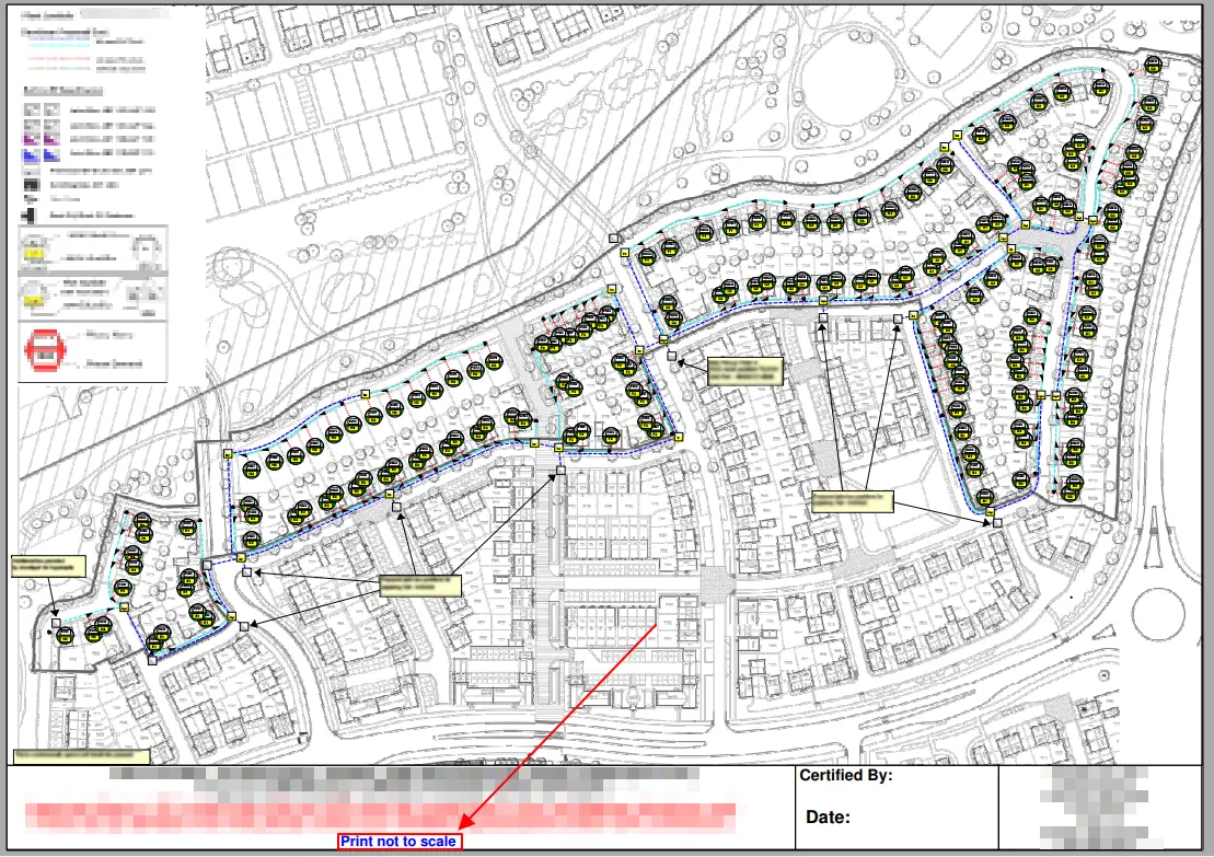
Pic. 1 PDF drawing ready for georeference in AutoCAD LT, Print not to scale.
There are two ways of importing this drawing to the AutoCAD LT. The longer and shorter. In our case, we will use the shorter, although the longer way can be also mentioned here.
The longer way requires the following steps:
– Typing the ATTACH (or PDFATTACH) command
– Selecting the PDF file from our directory after the dialog window opens
– Place your PDF drawing on the AutoCAD project (i.e. by specifying the location or scale on the screen)
– Select the imported PDF drawing (make it active) and check the PDF Underlay options displayed on the top (Pic. 2).
– In default, you will see the Show Underlay and Enable Snap options switched on. Show Underlay displays the content of your PDF document. Enable Snap to help you place the PDF drawing amidst other elements on your project, but works only for vector PDF files.
– Import as Object (does the same as PDFIMPORT command) to extract all the vector layers from your .pdf file
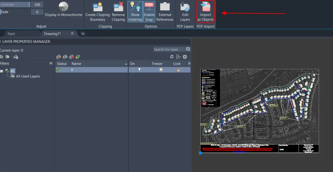
Pic. 2 The PDF Underlay options in AutoCAD LT. If you need to break down your .pdf file into separate layers you must select the Import as Objects option, which does the same job as the PDFIMPORT command.
The quickest option is just typing the PDFIMPORT in the command, but it’s vital to have another thing before we begin to import PDF drawings to our AutoCAD project.
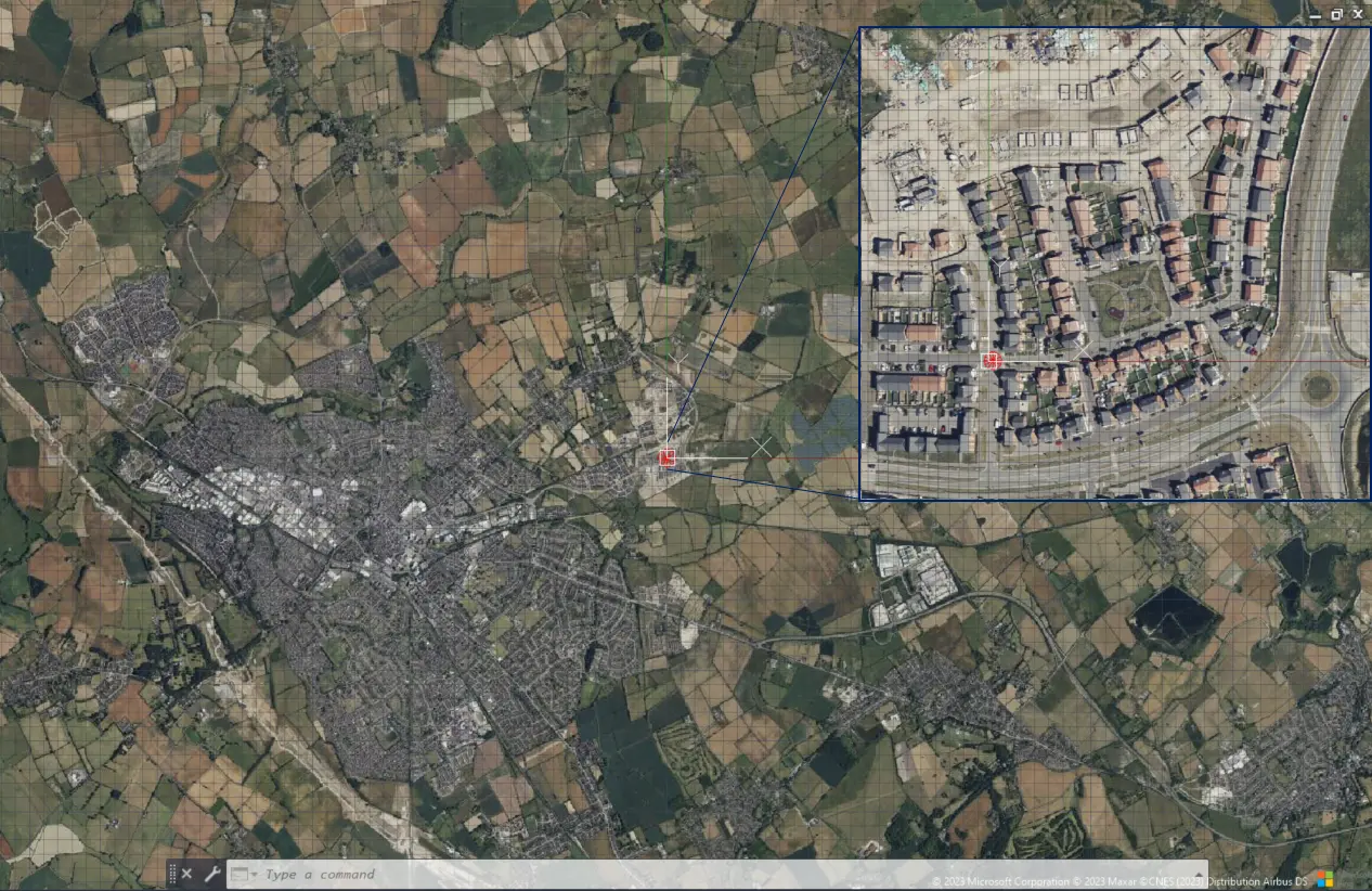
1. Type the GEOGRAPHICLOCATION in the command (1) to trigger the Set Location option (Pic. 2). Next type F as you want to select the file. Next, select your file when the dialog window opens. Next AutoCAD will ask you about the source of the geolocation. If you don’t have the .kml file prepared for this task, then type M for setting location from Map (2). Next, you will need the location. If you know your postcode, then it’s perfect. If not, type the town where you are working (3) and AutoCAD will propose it for you with the Drop Marker Here option roughly in the town center (3a). Assuming, that you exactly know where your working area is, but you don’t know the postcode, you can simply drag the map and right-click on the desired place where your marker will be dropped next (3b).
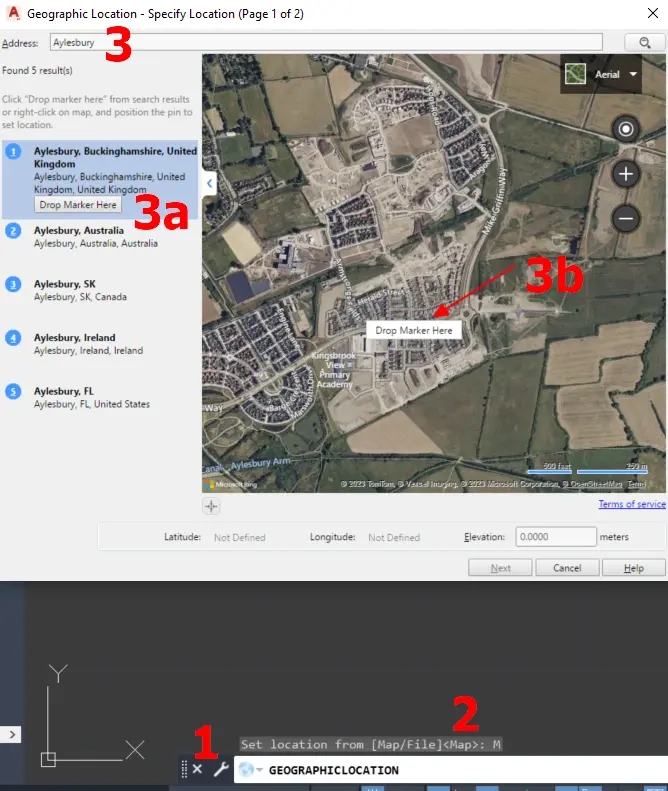
Pic. 3 The Set Location option in AutoCAD LT is done manually.
When your marker is dropped, you can click the Next button, which becomes active.
After that, you have to select the correct GIS Coordinate System for your working area. When dealing with the United Kingdom the best option is choosing the OSGB1936NationalGrid (Pic. 4). Hit Next when done.
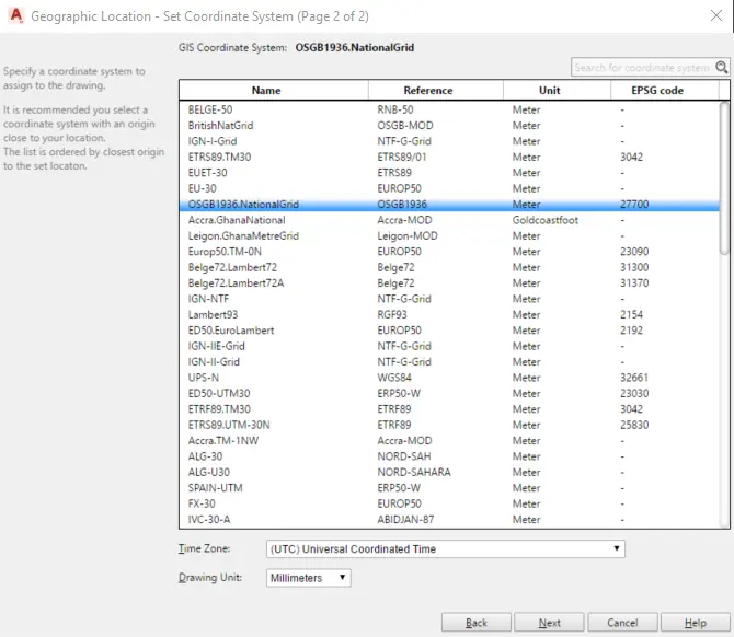
Pic. 4 The second step of setting location in AutoCAD LT – GIS Coordinate System selection.
The last thing is making the map embedded into the AutoCAD LT project by defining the basic (0,0,0) location and north direction (Pic. 5). Everything can be done smoothly with a couple of clicks.
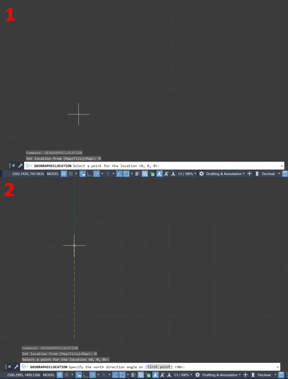
Pic. 5 Setting location in AutoCAD LT by defining the basic location point (1) and north direction (2).
Finally, you will see the Google Satellite imagery in your AutoCAD LT project (Pic. 6) with all the options discussed in this article.
Pic. 6 Our location is set in AutoCAD LT.
2. Type PDFIMPORT and hit F to load the .pdf file into AutoCAD LT. The dialog box will be opened, where all default options are fine. Worth looking at is the Location section, which specifies the on-screen insertion point as well as the Scale and Rotation of our PDF drawing (Pic. 7).
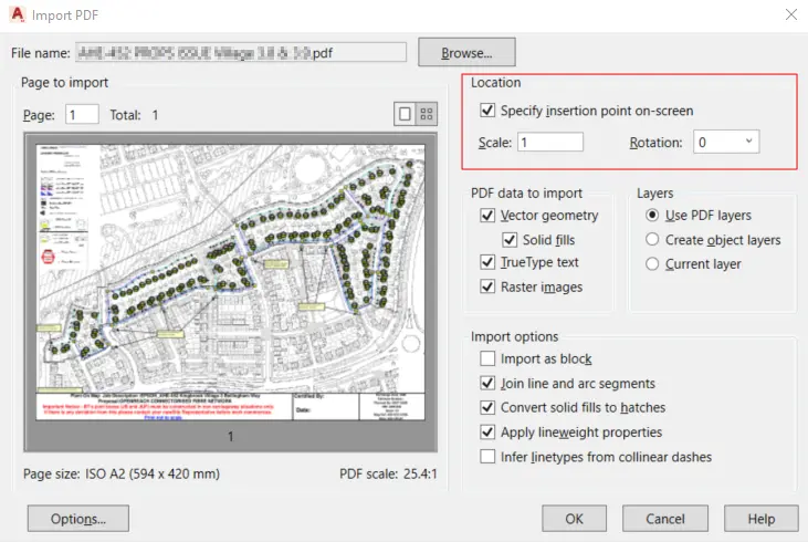
Pic. 7 PDFIMPORT options in AutoCAD LT where the Location section is the most important.
Since our AutoCAD Project has its location, the Specify insertion point on the screen seems to be the best option, because we can simply point out the exact place where our .pdf file content will be located. We must remember, that the insertion basepoint of our PDF drawing will always be 0,0 (bottom left corner). Assuming, that we don’t know either the true scale of our PDF drawing or the rotation value, we can just “place” our drawing on our project and see what it looks like. Because the document wasn’t scaled before it, we shouldn’t expect that it will fit our map straight away.
When clicked anywhere on the map, AutoCAD LT starts loading our PDF drawing, which takes some time, as it breaks down our drawing into separate layers (Pic. 8).
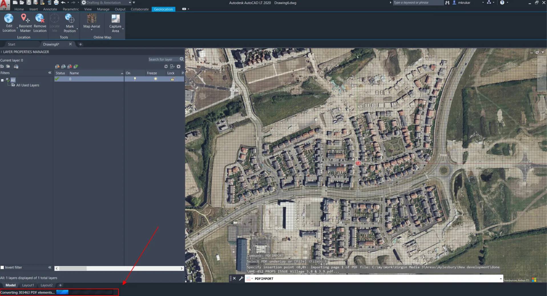
Pic. 8 Executing the PDFIMPORT command in AutoCAD LT where the location has been set.
3. Our file has been successfully imported to the project because all the layers are displayed correctly in the layer panel (Pic. 9).
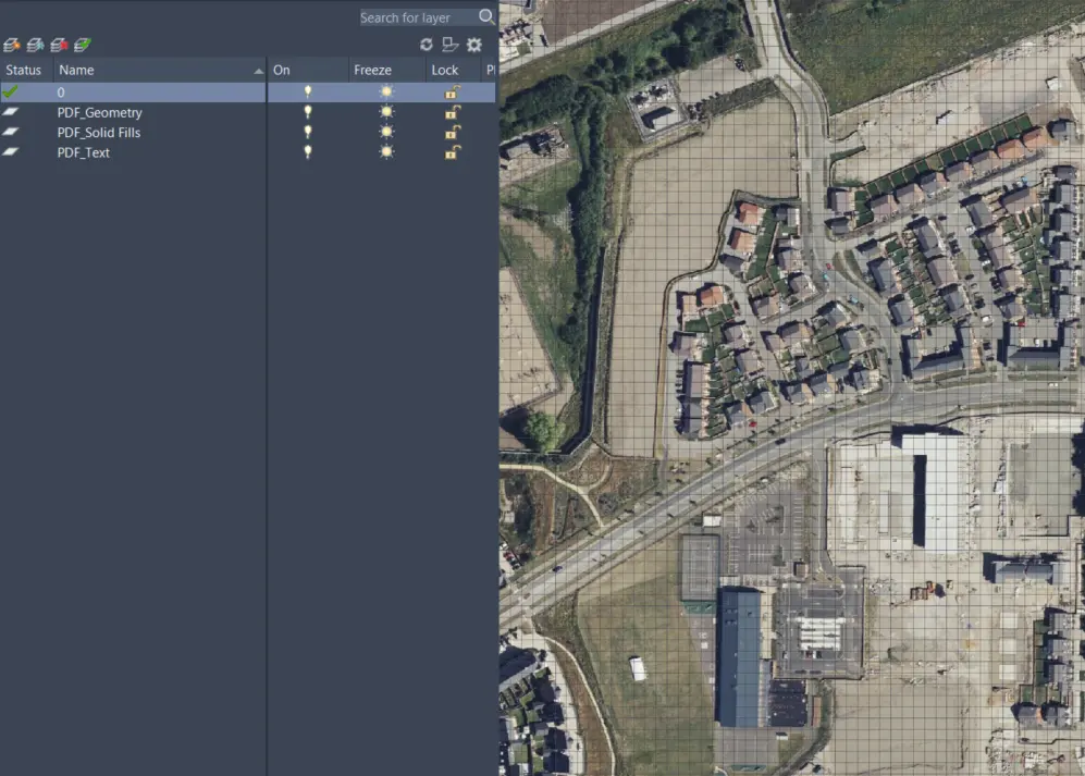
Pic. 9 Our PDF drawing was imported to AutoCAD LT, as all the layers can be seen on the left.
Unfortunately, something must be wrong, as the drawing isn’t seen anywhere.
If you are struggling with finding the object, the best option is to hit ZOOM in the command and choose the appropriate option, for example, E (Extends). If it doesn’t work probably slightly more advanced approach will be needed.
Right-click on the screen -> Quick Select and define the criteria based on the layers received from your PDF import (Pic. 10).
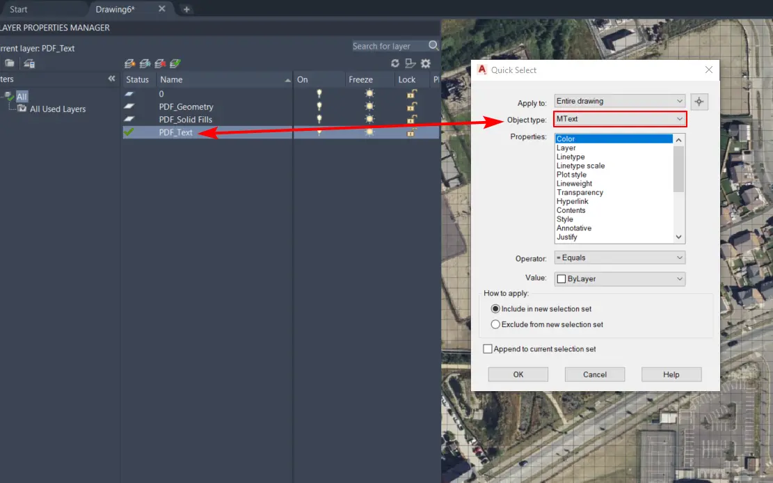
Pic. 10 AutoCAD LT Quick select options with criteria adjusted for the Text layer extracted from our PDF drawing.
Because one of the layers received from the PDF drawing is the text (PDF_Text), we can use the MText as the Object type. The MText occurs typically for text layers imported to AutoCAD, which was mentioned in this article. Once something is selected, above the console you will see the information that some number of item(s) selected. Next, we can select the properties, although they aren’t important that much. When done, click OK and type the ZOOM + O in the command (Zoom to object). Our drawing should finally appear in the middle of the screen (Pic. 11).
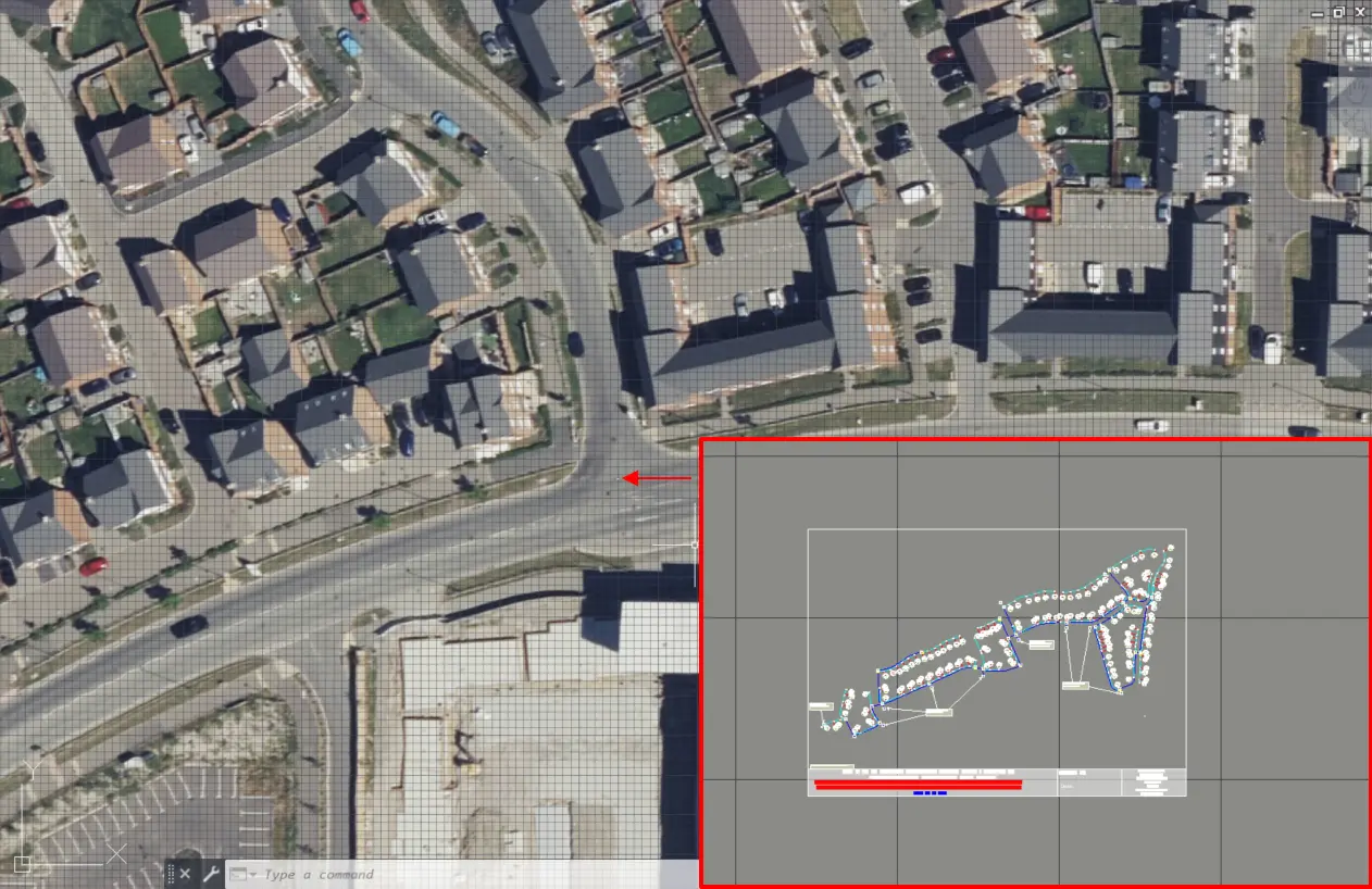
Pic. 11 Our PDF drawing is finally located in the AutoCAD LT project but is extremely small.
Our PDF drawing is extremely small. Anytime when the insertion is specified on the screen you should see the white box stuck to your cursor. The size of this box indicated the real size of the PDF drawing defined both before import and in the dialog window. If it doesn’t appear it means, that the object is very small. Returning to the moment, where I explained the Location section in the PDF Import dialog window, you can set the scale of 10 or even 100 instead of 1 and the box will be seen. In my case, it was 1000.
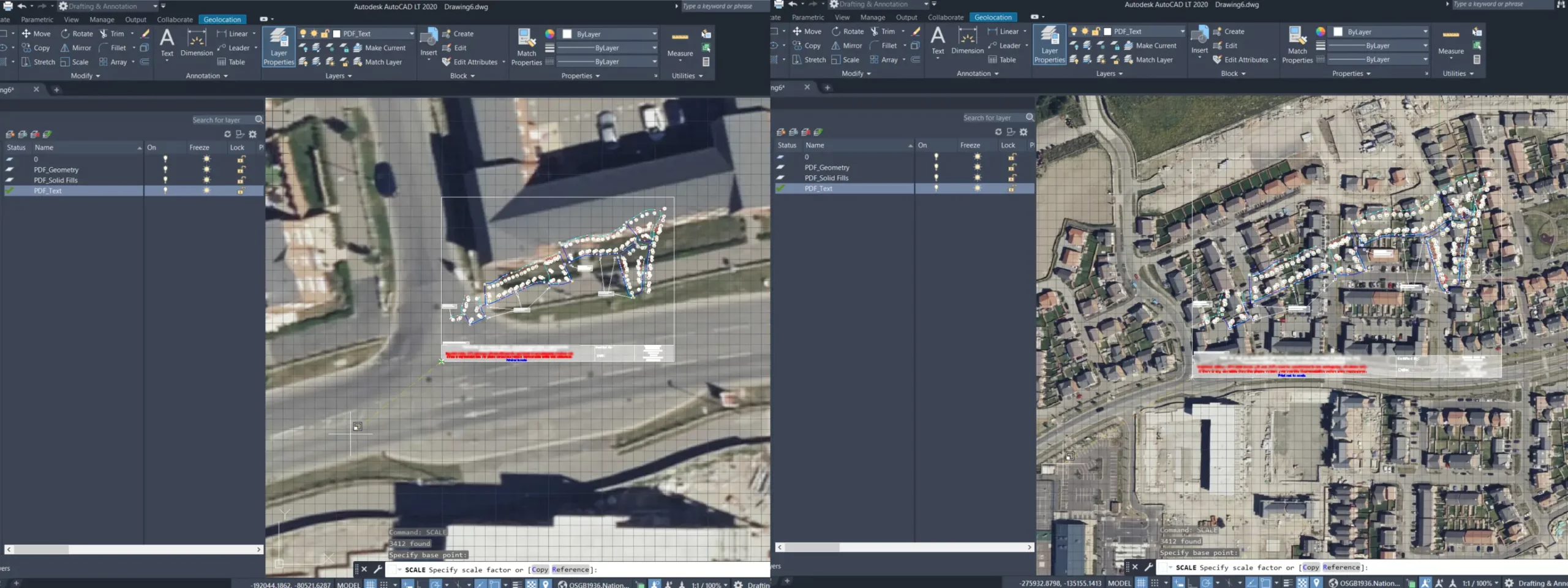
4. Select the entire drawing (1) and type SCALE in the command bar. Next, specify the basepoint (2) and specify the scale factor (3) (Pic. 12).
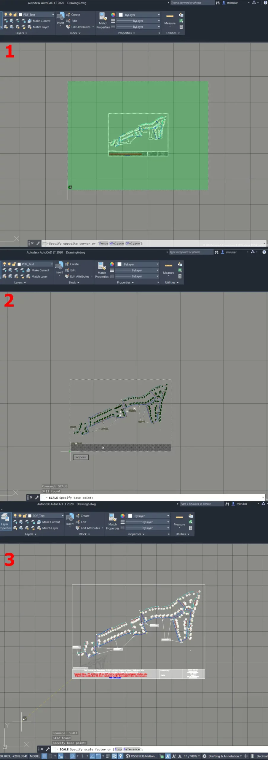
Pic. 12 Scaling our imported PDF drawing in AutoCAD LT.
If you don’t want to do it manually the SCALE command asks you to specify scale factor or Reference. You can also change the scale of the selection by leaving the original one in place (Copy), but it’s not needed in our case. By specifying the scale factor the result will be immediate after applying (enter button), when selecting the Reference option, you would need to define the Reference length and the points along which the scaling will be done. The quickest option is doing it manually because you can see when exactly the drawing will be fitted with the map (Pic. 13).
Pic. 13 Manual scaling the imported PDF drawing in AutoCAD LT based on the Google Satellite Imagery map below.
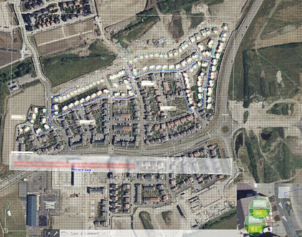
In the meantime, the whole drawing will require movement to the place where it will suit the satellite imagery below.
Pic. 14 PDF drawing suits more or less the map in AutoCAD LT.
5. In some cases a small rotation can be required. For this purpose, you should hit ROTATE in the command bar, which works analogically to the SCALE one, where the basepoint must be defined, next rotation angle or reference (Pic. 15).
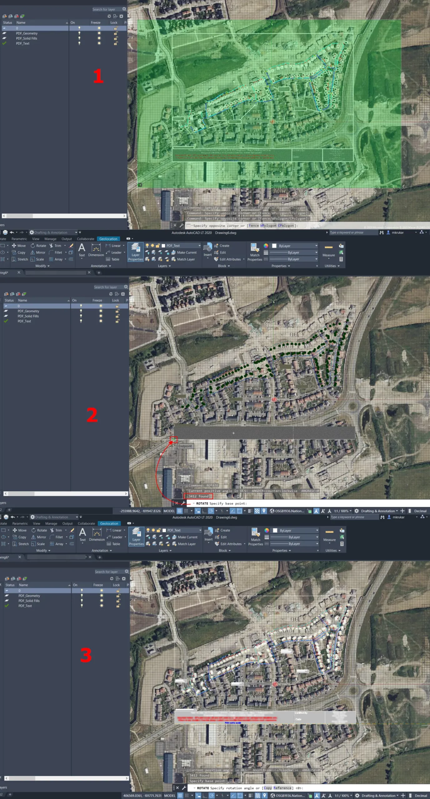
Pic. 15 The rotation of our PDF drawing imported to AutoCAD LT, where: 1 – Selection of the whole drawing; 2 – Specification of the basepoint; 3 – Manual rotation with other options.
The manual way probably won’t work as efficiently as previously because we need to be more precise to fit our drawing to the real situation as displayed in Google Satellite map. Instead, the Specify rotation angle option will be better, especially since decimals are accepted here too.
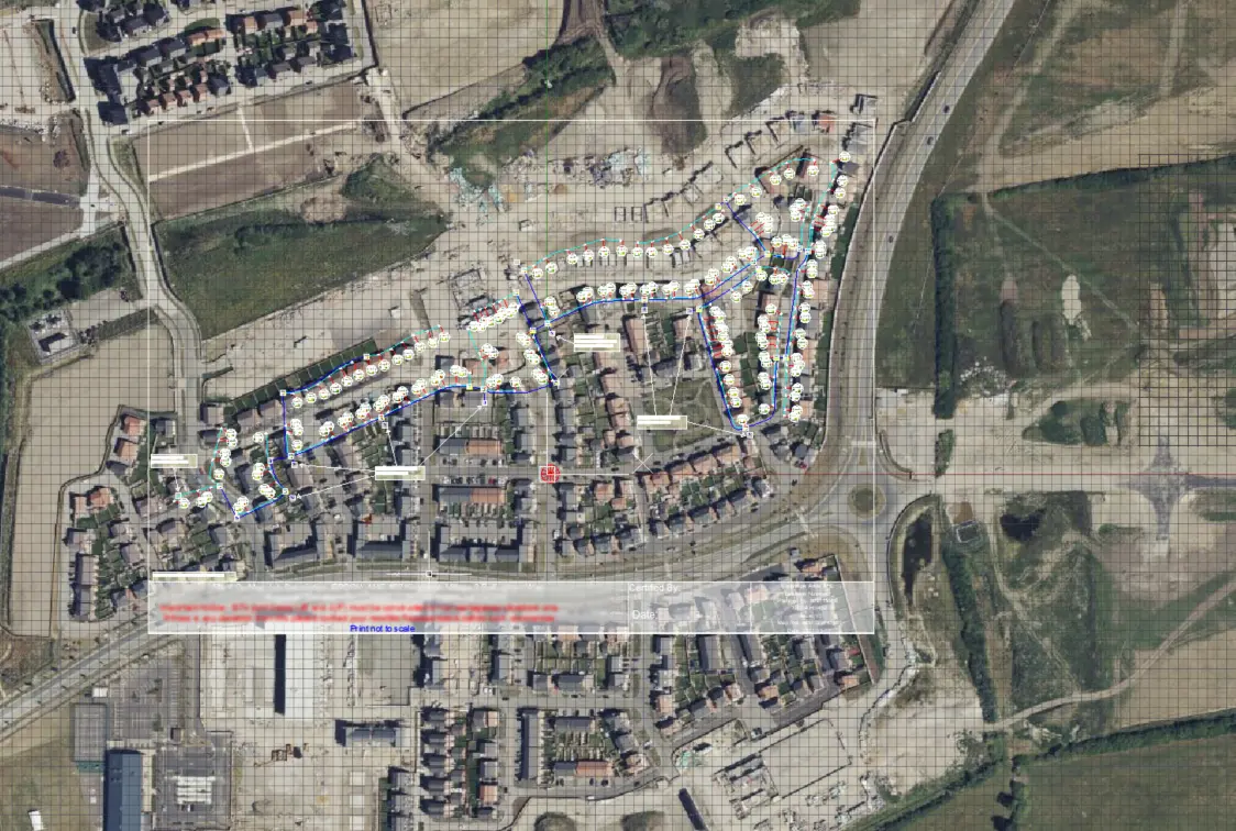
6. Finally you should see the imported PDF drawing which is embedded exactly in the place where it should be (Pic. 16). It can be used later in your AutoCAD LT projects wherever needed.
Pic. 16 The PDF drawing has been geolocated successfully in AutoCAD LT.
Now, when everything is completed you can use this drawing in other projects by using the PASTEORIG command. It will always reflect the georeferenced properties. You can make the georeference not for all layers but just for these, which are needed for further work. They can be removed both at the beginning or at the end of our process.
Mariusz Krukar
Links:
- https://www.adobe.com/acrobat/hub/why-pdf-is-best-format-for-business.html
- https://www.cad-elearning.com/autocad/how-to-georeference-a-pdf-in-autocad/
- Help.autodesk.com: Use Object Snaps With PDF Underlays
- Help.autodesk.com: GEOGRAPHICLOCATION (Command)
Youtube: