
The Magicplan is an Android application, by which we can quickly draw the floorplan of any building i.e. camera scanning or corner defining. The spectrum of options looks wide, even in the free bundle because we can add some internal objects and furniture. This is the stuff, which is mostly needed for common work projects. Unfortunately, the application is not free. If we want to have all these features possible to save in any reasonable drawing format given, we have to purchase the standard subscription, which will cost us about 10$/month.
In this post, I am leading to explain to you, how to get over these frill costs and get as many floorplans as you need completely for free!
After reading this post, you will know how to:
– resize the page to the content in the content in Inkscape,
– convert the raster image to the vector image in the Inkscape,
– do simple vector drawing alterations in the AutoCAD
In general, the basic 3 steps are needed to get any floorplan saved from this application.
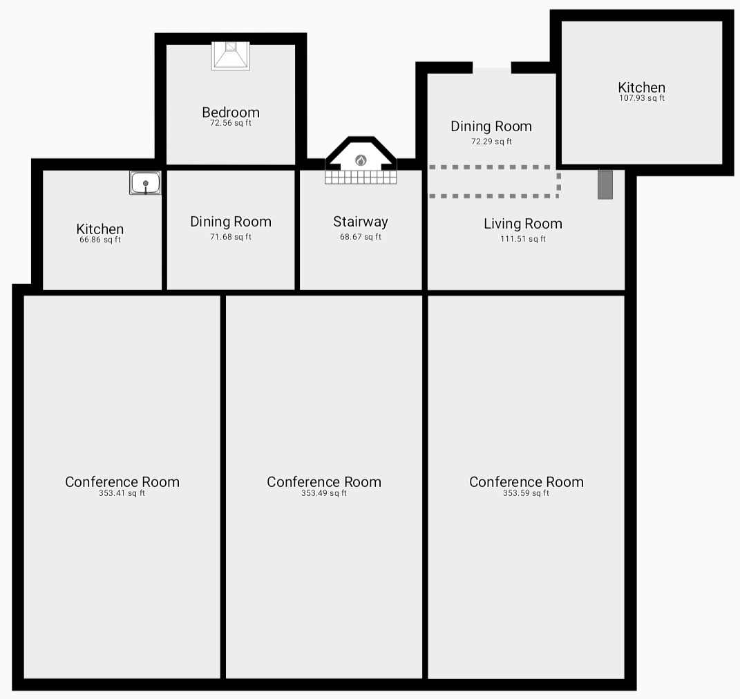
1. Make and edit the screenshot from your smartphone. Once your floorplan is ready, the first thing should be done. Thereafter, we have a crude .jpg image of our plan as follows (Pic. 1).
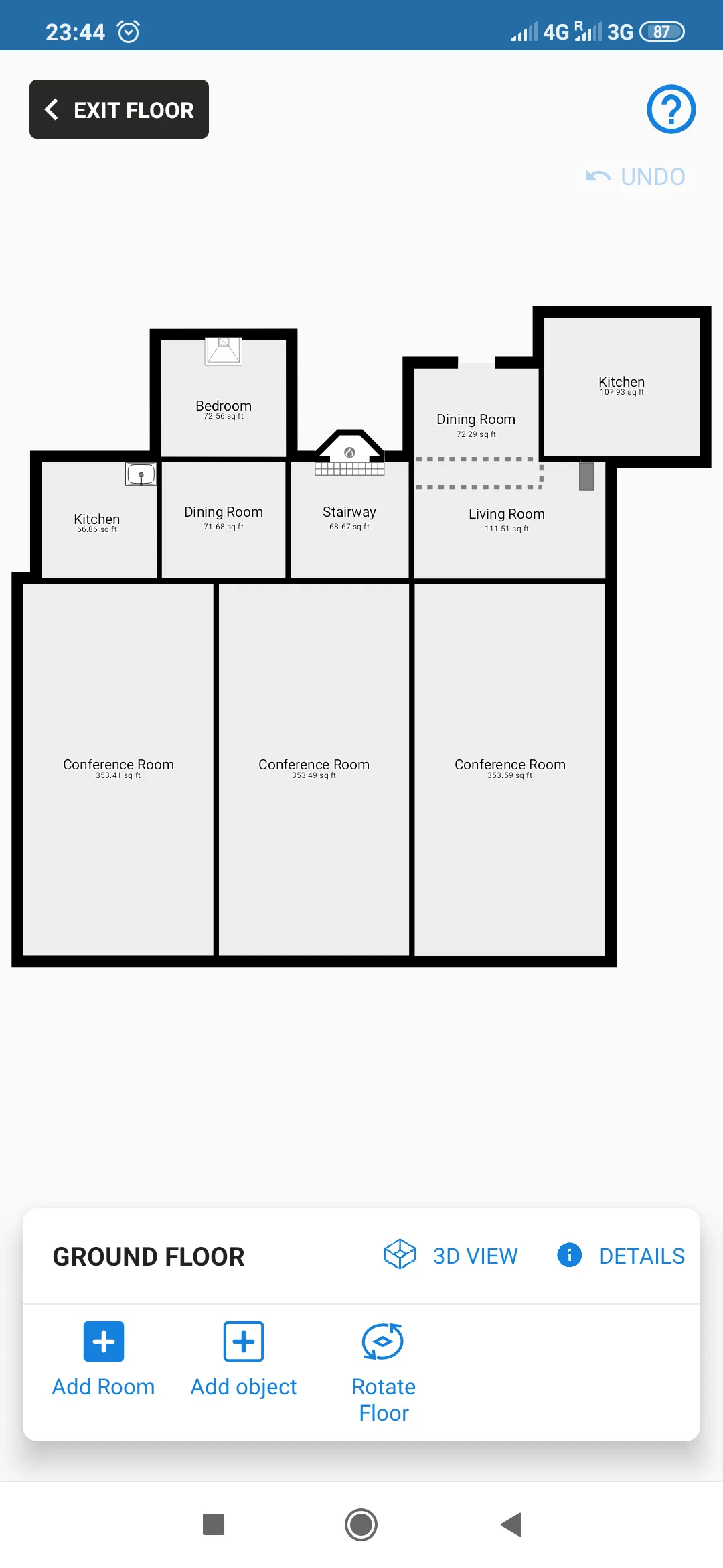
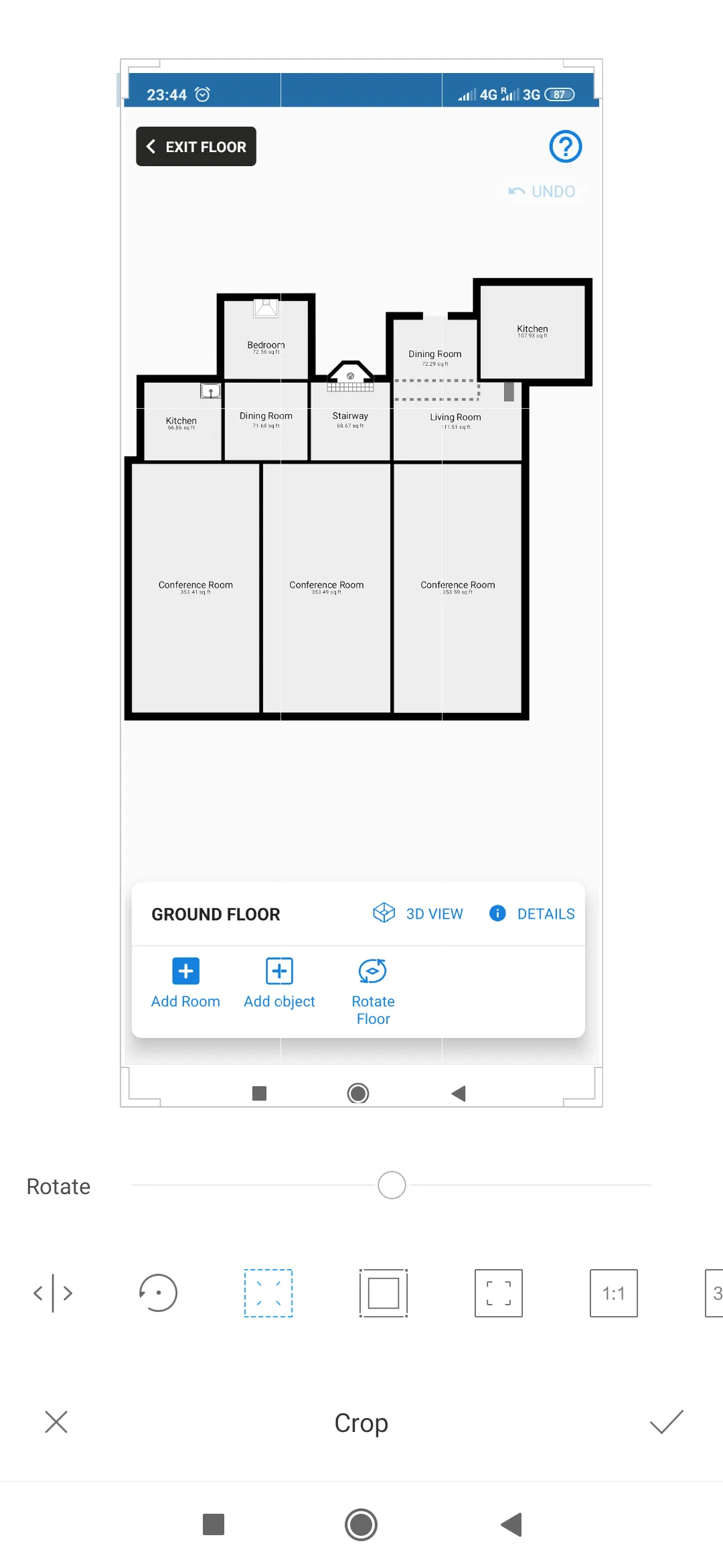
The screenshot looks not enough prepared for our further work. Since apart from the floorplan, a whole screen is coming from the phone, we must adjust this image for further action. I believe, that most of the basic smartphone editors are equipped with the “crop” tool. This feature is necessary to make our floor plan clean (Pic. 2,3).
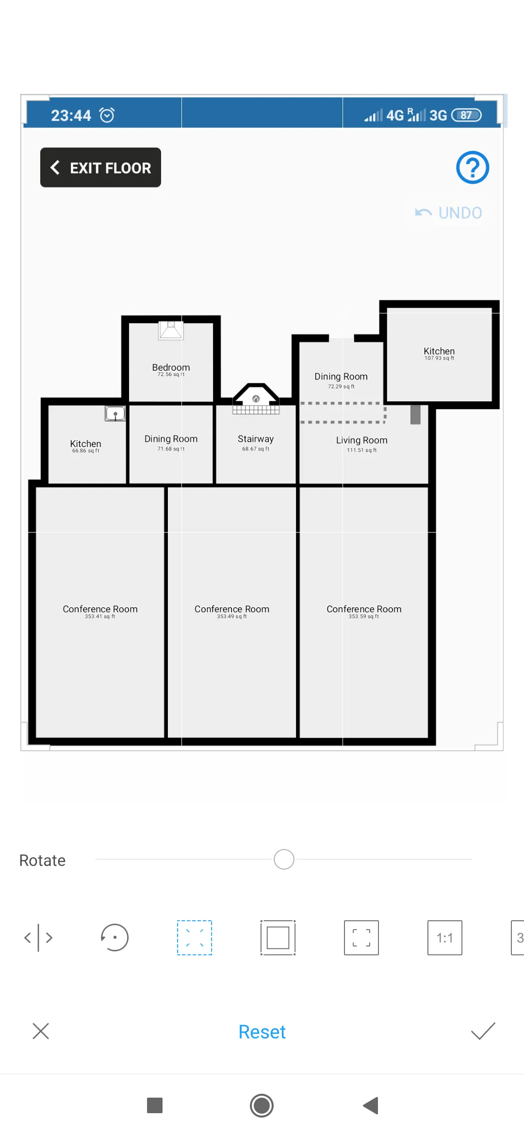
Our output .jpg image of the floorplan shouldn’t contain any additional elements outside (Pic. 4).

If this is so, then we can go to the next step, which is transforming our raster floorplan into a vector image.
2. Convert the raster image into a vector image. Assuming, that everything is fine with getting our floorplan from the screen, we can open some vector graphic manipulation software, for instance, Inkscape, and import our image there (Pic. 5).
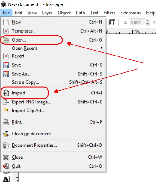
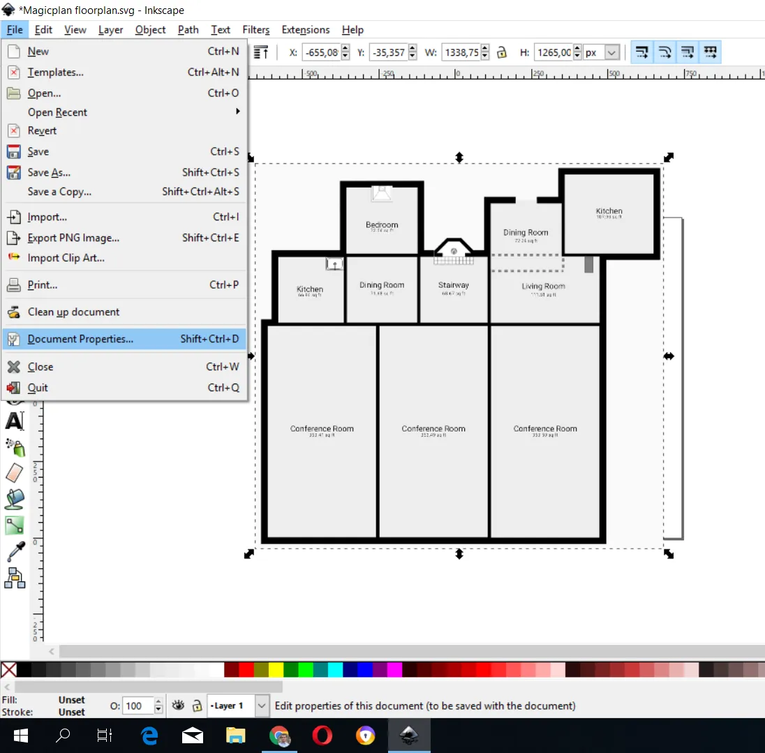
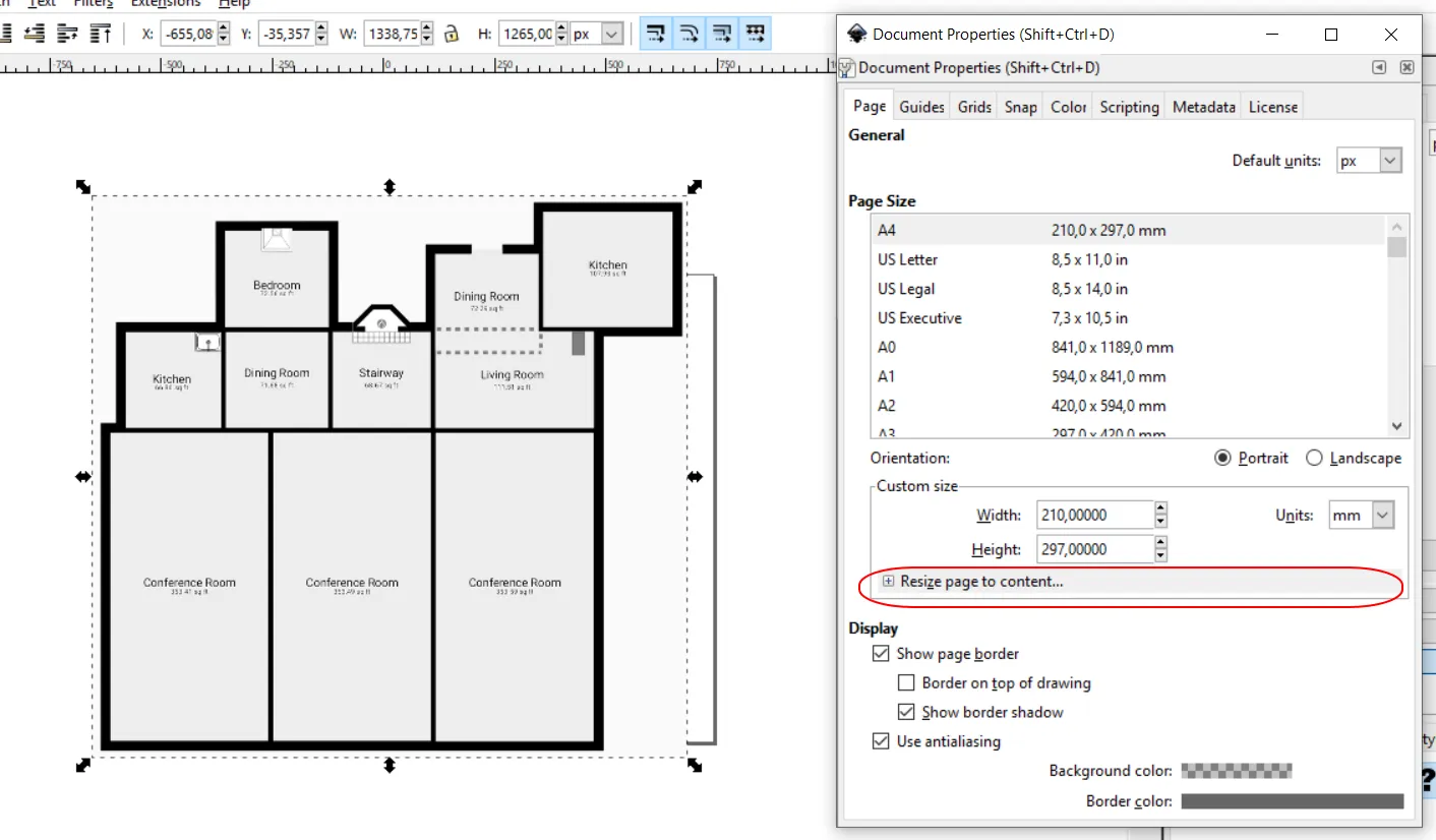
For this purpose, you can use the “Open” file, or the “Import” file either. Both options are valid. The difference between them is the number of windows. Opening the file triggers a new working window of the Inkscape program, whilst the “Import” option will let you work in the already opened document. Once you do it, MAKE SURE that your document is placed inside the document page! Otherwise, even after the best process, it won’t be saved properly. In order to make sure, that this step is done, select the “Document Properties” from the “File”, and find the “Resize page to the content”, as follows (Pic. 6,7).

Next, develop it, by clicking “+”, where you will be able to set the proper document size by clicking “Resize page drawing to the selection”(Pic. 8). Instantly after clicking the button, the change appears (Pic. 9AB). You don’t need to do anything after it, just close the window.

When this adjustment is done, it’s time to start converting our floor plan. Because it has been imported as a .jpg format, it’s the raster image. To have it viable for use in AutoCAD, Visio, or other drawing software applications we have to get the vector image of our floorplan.
This process is quick and simple. In the major toolbar, we must find the “Path” option and next click on the “Trace Bitmap” feature, which will do a whole job for us (Pic. 10).

The “Trace bitmap” window should appear straight afterward (Pic. 11). It would be good to see our real-time image changes, so I advise you to thick the “Preview” option on the bottom right corner.

The most important option for us is the vector image path creation, which has 3 major options. I used the “Brightness cutoff” – the very top one from the list. Look at the threshold value and observe what happens in your preview mode. As you change the threshold value (It would be advised to put higher, than lower), your proposed vector image should change. It’s nicely visible on less prominent elements of our floor plan, especially these, which aren’t completely dark (Pic. 12, 13).
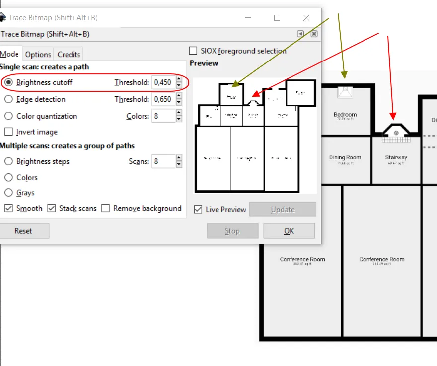

The live preview option prevents you from exaggerating the image performance. Try to input the 0,99 value and see how your floor plan is turning into the dark. In my opinion, an optional brightness cutoff threshold value for a clear floorplan appearance with all objects included is about 0,800-0,880.

If you are happy with these parameters, just click the OK button and see what happens. Bear in mind, that our vector image has been created roughly in the same place as the existing raster one. In this event, you can spot how unusual thickness and boldness emerge. Because our newly created vector plan appears as a top layer, we can simply select it and drag it outside the drawing page (Pic. 14).
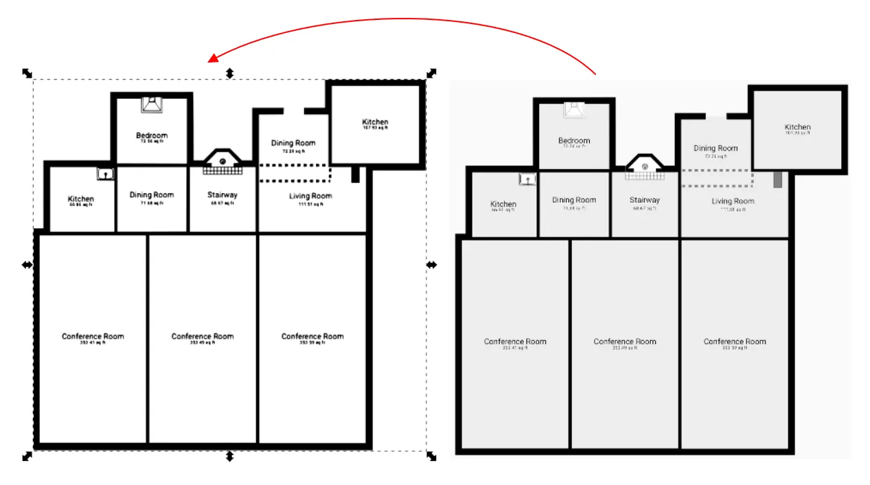
This step is good for comparing images. When you are unhappy with your fresh vector image plan, you can always repeat the process, changing the parameters, since the preview option is almost a thumbnail. Personally, I think, that it happens only rarely.
Well, assuming, that everything is fine, we can now delete our raster floor plan and supersede it with the vector image. Simply click the “Delete” button on the raster image selected, and drag back the vector floor plan inside the drawing page (Pic. 15).
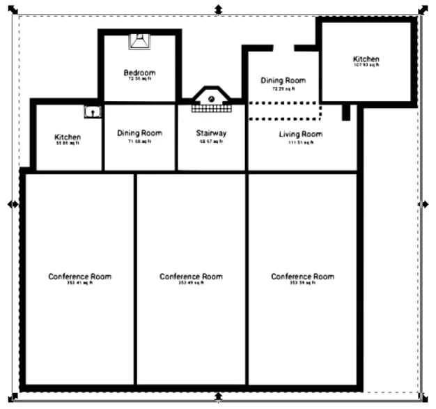
Unlike the previous raster floor plan, the document page edges are clearly visible, as the white background has been completely removed.
Our last step in the Inkscape is saving the file in the DXF format, designated for the AutoCAD drawing application or similar (Pic. 16).

3. Now you can open your floorplan, for example in AutoCAD, from where my example comes from (Pic. 17).

It’s advisable, at the very beginning to type the “Pan” in our command bar. Once the hand cursor appears, move your view to the middle and do some zoom in/out to make sure, that it has been imported correctly.
At first look, we can see some unnecessary lines (Pic. 18).
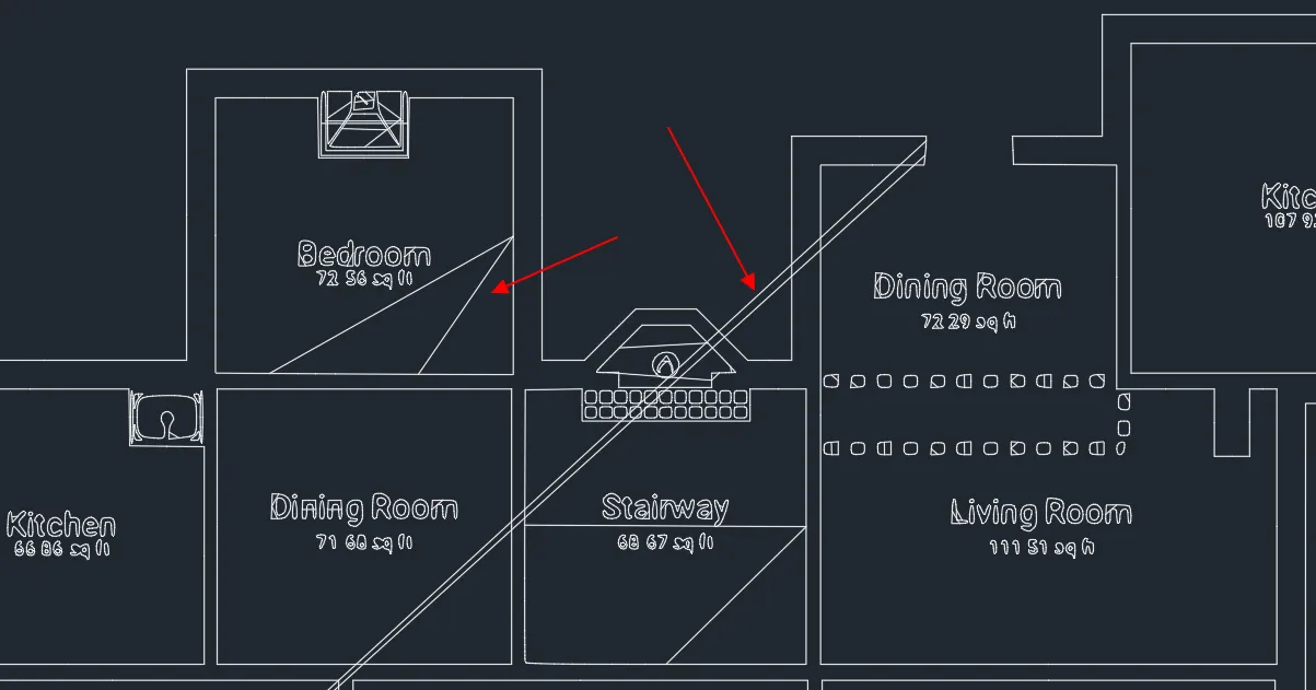
Fortunately, we can easily and quickly get rid of them, using the “Trim” tool from the main toolbar (Pic. 19). You can also use the “Erase” tool, however, it will remove the whole shapes instead of their pieces.

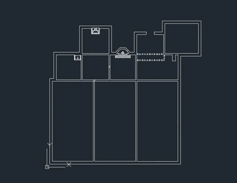
As a result, you should get the floorplan clear and tidy, as per below (Pic. 20).

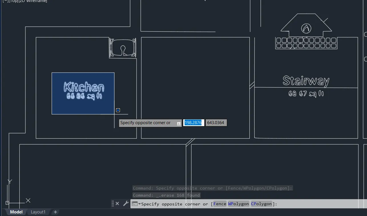
The last thing, we would consider is the text, which is displayed here as enclosed smallish polygons (when you zoom in). I believe you won’t need it for your future work, or provide the better one with AutoCAD. It can be removed here easily. You can only select the area, where you will be working. Afterward, you will see the blue triangles, circles, etc. showing the selected text polygons mentioned above (Pic. 21).
At the finish, your floorplan should look like this below (Pic. 22).
In summary, I would encourage you to watch the video below, explaining these basic and major three steps of our work.
Basically, you need a decent screenshot from your smartphone, some vector graphic manipulation tool, and AutoCAD or similar.
Mariusz Krukar
Read also:
1. How to show coordinate grids on Google Earth and Google Maps?
2. Flood simulation in Google Earth
3. How to make isochrone map in Google MyMaps quickly?