Good solution to georeferencing the AutoCAD DWG drawing in QGIS 3x
Today I would like to demonstrate how to georeference the AutoCad .dwg file in QGIS. The .dwg extension keeps layers, colours, line thickness etc. in other words all information included in the drawing file. This is the biggest advantage of drawing files over another AutoCad extension – the .dxf. This format, on the other hand, doesn’t contain all the features mentioned previously. It retains only the linework, dimensions and text. This is what makes these files – drawing interchange files more versatile in the GIS environment. Going this way it should be easier to manipulate the .dxf file in other GIS applications, i.e. QGIS. Nobody should wonder, that we can easily plot the .dxf file into QGIS adding it as the simple vector layer. The .dwg layer is slightly different because have to import it separately.
The way of importing the .dwg file to QGIS has been widely explained on the web before. I am focused on the steps forward.

Pic. 1 Importing .dwg file to QGIS
When your file is imported (right after clicking the OK button) it should appear as the layer group name, which we provided in the “Group name” input (Pic. 1).
This group of layers can be easily expanded (Pic. 2).

Pic. 2 The .dwg file was imported to QGIS.
The next step should be the right-click on this layer group and move it to the top in order to make it visible above all other layers.
Because our Autocad .dwg file comes now as the package layer (.gpkg), we can easily get access to all visible layers and manipulate them.

Pic. 3 The AutoCAD .dwg file is now the geopackage (.gpkg) file in QGIS.
When you see the above image, you probably are wondering where your AutoCAD drawing is placed. The blank background means that it’s definitely not where we want, as we already have the map canvas imported for our location (Pic. 1, Pic. 2). Now is the time for georeferencing our drawing. It can be accomplished in 2 ways, whilst the second one will work only when you have some previous job nearby.
There are basically 3 ways in QGIS of georeferencing the vector layer:
– Affine transform
– v.transform (GRASS)
– Transform vector layer (SAGA)
The last one appears to be the quickest for our purpose. Launching the Transform vector layer tool we have a few inputs (Pic. 4).

Pic. 4 Transform Vector Layer option in SAGA.
- “Shapes” section – the tool already selected the active layer, which we are dealing with
- Dx, Dy – accordingly X and Y coordinates in which our vector drawing is going to be georeferenced
- Angle – the optional rotation of our drawing against the QGIS map canvas
- Scale factor X and Scale factor Y – the drawing rescale across the X and Y coordinates
- X, Y – the coordinates of the centroid of our drawing, useful in the rescaling process
By now we just need the Dx and Dy input in order to georeference our vector layer. If you are in the UK, you can use the Gridreferencefinder platform to define the Ordnance Survey coordinates for your area. If you are outside of the UK you can use the standard UTM coordinates.

Pic. 5 Input the valid coordinates for the transform vector layer tool, where: 1 – the QGIS layer defined with the appropriate CRS (British National Grid 1936, EPSG27700); 2 – X – easting; 3 – Y – northing coordinates.
The X and Y are elements of the Cartesian Coordinate System. It means, that your coordinates should come from the South-west edge of your drawing (Pic. 6).

Pic. 6 Place your drawing in the Cartesian coordinate system (Wikimedia.org).
Once you provided the coordinates for your layer, just go OK and see what happened. You have got already a separate layer called “transformed” (unless you previously indicated the other name and the directory for the new shapefile), which is temporary. The most important thing is, that you can see already your layer on the map very close to your target location (Pic. 6). Obviously, some smallish alterations are required, but we can deal with them a bit later.

Pic. 6 First layer transformed in QGIS and present in proper or at least estimated location.
Now I would advise you to right-click on the “Transformed” layer, which is temporary (rectangle signature on the right), next select “Export” -> “Save features as” and save it as the shapefile in the directory.
Repeat the process for all remaining layers keeping exactly the same coordinates. As a result, you should see your whole shape in the desired location (Pic. 7). In the meantime you can remove all old layers at once, keeping your group tidy. Remember, that now your file lost all of the details from Autocad or similar software because we saved it in the shapefile. It’s a pure vector shape including lines, dimensions, and objects. Even the text is gone. Everything must be customized here.
Pic. 7 Our former AutoCAD drawing can be seen in QGIS at the proper location.
Another matter indispensable to the georeferencing of our object is rescaling. Basically, we don’t know at the initial stage how our drawing will correspond with the map since we haven’t dealt with setting proper scale before. Assuming, that you were focused on drawing and omitted any cartographic issues in AutoCAD or similar software, it will be needed for you now. Once you imported successfully your drawing to QGIS and place it on the map canvas, like I did above (Pic. 7) there is an easy way to gauge the difference of the scale at the area affected by our drawing. Most of the time the rescaling process is needed. In this event, we should use one of the three georeferencing vector layer tools mentioned above. I am standing by SAGA’s transform vector layer.
If you have in mind the screenshot above (Pic. 4), where I described all inputs in the Transform Vector Layer tool, there are others to fill in this time. Namely, we must set the scale factor (change it from default 1.0) and define X and Y coordinates (Pic. 8).

Pic. 8 Things to input in SAGA’s Transform Vector Layer when rescaling your feature – setting the scale factor and XY geometry.
We can put the same XY coordinates, as we did for georeferencing our vector layer. In turn, we should see another shape appearing just next to the first one (Pic. 9).
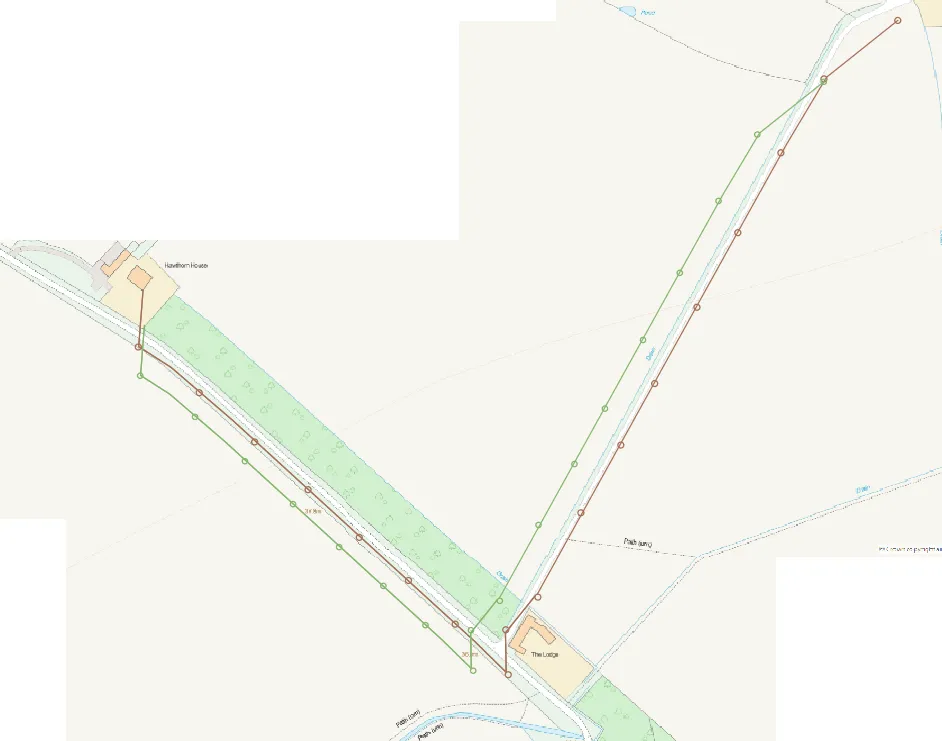
Pic. 9 Rescaling our AutoCAD drawing in QGIS, where the green shape is our new one.
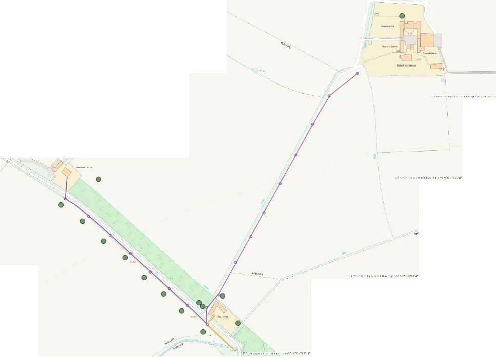
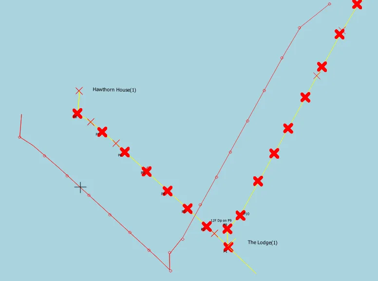
You can see the brown and green vector shapes above (Pic. 9). The brown one is our older shape, which was just georeferenced. The green one is the new one, already rescaled from the first one. After all, we must move our rescaled shape to the place, where it should be. In our case, the brown one has to be replaced with the green one, which matches the on-the-ground situation (Pic. 10).
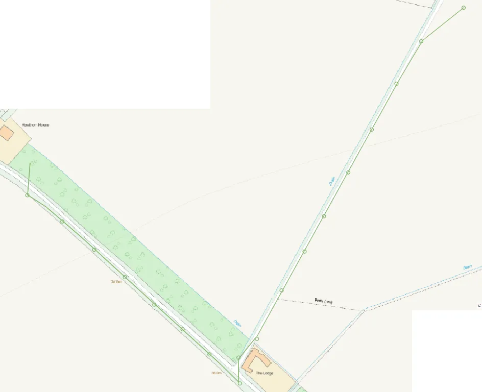
Pic. 10 Our rescaled AutoCAD drawing in the right location.
The second option is also worth attention. Especially, when we already have some job visible or finished in our area and we are going to expand our work in a neighbour region. In this situation, you need to import the AutoCAD drawing and make it displayed in QGIS (Pic. 3) as a first step. Next, I would advise you to launch the OpenStreetMap layer in QGIS from the “XYZ Tiles” panel (Pic. 11).

Pic. 11 Our not georeferenced AutoCAD drawing was placed at the OpenStreetMap canvas in QGIS.
If you are working within some national coordinate grid system, like the British National Grid, then your layer is to be placed at the “very beginning” of these coordinates according to the Cartesian coordinate system. In this case, when you keep on zooming out i.e. by your mouse wheel, you should see its location (smallish black dot) against the nearest land, or eventually, the last area where you worked (Pic. 12).

Pic. 12 Manual georeferencing vector layer in QGIS, where: 1 – our new layer with undefined coordinates; 2 – our another vector layer already georeferenced in QGIS.
When you already got around and know more or less the current location of your not georeferenced layer, you can simply move it towards the target location. In order to do this you need:
1 ) Select the layer, that you are going to work on
2) Toggle edit mode and turn on the Advanced Digitizing Toolbar if you don’t have it yet (right-click on the “Edit mode” yellow pencil and select it from the “Toolbars” section.
3) Select our layer using the “Select features by area” option
4) Toggle the “Move feature” from our “Advanced Digitizing Toolbar” and try to highlight your vector layer (it can be difficult when zoomed out, so you can zoom in to your layer a bit. When successful, you should see a pink rectangle (or cross) independent of the zoom level) (Pic. 13).

Pic. 13 The quick way of manual georeferencing the vector layer in QGIS, where: 1 – layer selection from the QGIS layers panel; 2 – toggle “Editing mode”; 3 – selecting feature “by area or one-click”; 4 – toggling “Move feature” option; 5 – highlighting our layer by a pink rectangle (or cross), independent of zoom level.
Since we highlighted our shape, we must just click once on it, sticking it to our cursor afterwards. Now, we still have our layer in its initial place, but the “new location” of our drawing is stuck to our cursor and marked red (Pic. 14).
Pic. 14 Moving our drawing in QGIS The new location of our shape is glued to the cursor.
The shape is glued to our cursor despite zooming in/out or moving the map unless we click somewhere. Then the shape is placed there. If you need to drag your map canvas, you better use the keyboard up/right/down/left arrows to do it.
This way you can set a new location for your vector layer. The process has been explained in detail in the video below.
Remember to rescale your shape, when it doesn’t fit your map scale. You can follow the instructions for SAGA’s Transform Vector Layer tool above.
It will be obviously harder, when you have no previous job displayed in QGIS, or when you used the WGS 84 or Pseudo-Mercator coordinates to start with. Nevertheless, following this mechanism, you should achieve this goal. The biggest advantage of this way is retaining all layer features (colours, thickness, etc.) customized yet in AutoCad or similar.
Georeferencing the .dwg file in QGIS was never so simple then. It’s up to you what way will you pick up in order to place your drawing in the correct geographical location in QGIS.
Mariusz Krukar
Links:
- Info about the .dwg extension
- Converting Latitude And Longitude to an X Y Coordinates
- Convert Lat Long to UTM
- Cartesian/Projected Coordinate Systems, UTM
- Convert between Latitude/Longitude & OS National Grid References
Forums:
- https://gis.stackexchange.com/questions/33208/georeferencing-vector-layer-with-control-points-using-qgis
- What is the difference between DWG and DXF files
- https://gis.stackexchange.com/questions/32730/importing-dwg-into-qgis-project
- https://stackoverflow.com/questions/62299676/dwg-dxf-import-in-qgis-fails
- Import Layers from DWG/DXF fail
- https://gis.stackexchange.com/questions/136817/qgis-moving-the-layer-all-features-using-vector-affine-transformation
- https://gis.stackexchange.com/questions/30559/computing-parameters-for-qgis-affine-transformation/127653
- https://gis.stackexchange.com/questions/222320/using-grass-v-transform-rotation-point
- https://gis.stackexchange.com/questions/350414/grass-v-transform-tool-producing-no-results-qgis
- https://gis.stackexchange.com/questions/273758/enlarge-a-polygon-without-changing-its-shape-or-position
- https://stackoverflow.com/questions/16266809/convert-from-latitude-longitude-to-x-y
- Confused by coordinate systems?
My questions:
- https://gis.stackexchange.com/questions/371329/qgis-3x-problem-with-rescaling-vector-shapefile-layer
Wiki:
- Cartesian coordinate system
- Easting and northing
- Ordnance Survey National Grid
- Universal Transverse Mercator coordinate system
Youtube: