Manual estimation of the visual range between two artificial objects – case studies
Anyone, who deals with long-distance observations knows all the most popular panorama or visibility cloak generators from the given place. Every user knows the primary malady of all these simulators – they’re based on the DEM (Digital Elevation Model) only. In practice, it means, that all the calculations are based on the pure ground with no forest, vegetation, and urban development too. Since a user can at least generate the visibility cloak from some hypothetic altitude, assigned usually to some existing construction or building, it will still cover the visual range based on pure DEM. Threading its way, the user is still not aware of the potential maximum distance of the line of sight from this viewpoint. In the world of mobile phones and media, we should take into account the local and regional transmitter distribution, which is sparkly quite dense, especially around large urban areas. Usually, but not always the presence of some telecom construction marks the highest or one of the highest points in the local area. It gives additional favorable conditions for the visibility cloak expansion from our elevated viewpoint.
This article should be an answer for the potential visibility conditions between one artificial object and another, as it shows the manual two methods of estimating a view such as this. The best simulator, which can be used for this purpose is Heywhatsthat, which gives us well-presented parameters of the considered line of sight.
The shape of this writing will be a bit different, than usual, as I am focused on the case studies.
1. INTRODUCTION
Considering the presence of any artificial objects being firmly integrated with the ground, we should be aware of their visual impact regardless of the distance to the observer. With this in mind, I would like to ask the following questions:
– how tall does the building stand above the horizon?
– against which background the building is placed?
– does it cast a shadow on certain places?
– how well is the object visible from a certain location?
All these questions are subject to the VIS (Visual Impact Size) method, which determines at some point the “reversed viewshed” defining, from where the target point is visible (Caha, 2017). The method is related to the extended viewshed, very important from the long-distance observation’s point of view. The Extended Viewshed approach calculates additional visibility depending on the distance between the observer and the height of the target point (Fisher, 1996). The Visual Impact Size method refers to the maximum height for each point in the given area, above which a given facility can be seen (Czynska, 2018).
In our case, the Visual Impact Size will refer to the remote tall construction or skyscraper visible above the horizon from the place, which normally wouldn’t be visible if it were lower. Considering only the distant object’s appearance, the Visual Impact Size won’t play a significant role, as it does within the cityscapes. However, VIS is “responsible” for any, even smallish change in the landscape caused by some tall construction until the edge of its viewshed. As was mentioned above, any elevations above the ground will result in the extension of the viewshed from that place. When the observer’s place is elevated by another artificial construction, then the viewshed gains an additional range. It has been also a subject of discussion occasionally, especially in relation to improving the effectiveness of watchtowers (Pompa-Garcia, et al., 2010), but mostly in terms of wildfires or some military purposes, especially in the past. Nobody considered the effectiveness of high buildings or tall constructions with respect to the maximum viewshed range, desired for long-distance observation purposes. This article should bring an example of answers about the target point visibility from some elevated location, which is firmly integrated with the ground. In this case, the viewable area won’t be limited to the area falling exactly within the line of sight from the top of some construction. The analogy we could see within the aforementioned forest-fire observation towers, where the person can detect the fire of remote forest not by seeing the local surface but by the smoke dispersed by wind, which is much higher. In a similar way, we can define the visual impact of an existing object, which is visible only because of its vertical difference between the ground and the visual line of sight.
In general, the viewshed calculation by using various GIS software seems to be very easy, unless we incorporate some build structures in our viewshed computation. Then our process becomes difficult, all the more that the heights of these buildings, as well as their shapes and locations, are often uncertain (Sander, Manson, 2007). Although most of these computations are able to bring quite genuine results if the proper amount you would need to raise the ground by to see the distant feature. Next to the vertical proportion, we shouldn’t forget about the horizontal proportion of the distant feature. It will, in fact, play a minor role in long-distance observations, but might happen quite often, that some remote construction will be too thin for the distinction by the human eye or even a telephoto lens. In fact, it still means, that they’re theoretically visible, by the omission of the height of the forest or atmosphere disturbance. Again, this article will show you the methods of how to check are the two distant man-made constructions intervisible or not.
2. CASE STUDIES METHOD I EXPLANATION
Before I start to analyze the particular scenarios I would like to focus on the general explanation of the matter in this article. As it has been told above, we deal with the line of sight possible to achieve between two artificial structures. It can be simply depicted by the image below (Pic. 1) where both tops of the towers are intervisible.

Pic. 1 The lines of sight between two artificial objects, where: A – tower 1 standing at a small hill; B – big mountain range; C – tower 2 standing at the big hill.
By watching the image above, you realize, that the “place C” elevated by the height of the tower couldn’t be visible from the tower standing at the hill “A” if the tower standing at the top of the hill “C” wouldn’t exist. This is how the visual range can be expanded by the initial DEM computations. I am convinced, that this issue is common worldwide, because of a quite high density of telecom structures coverage as well as the common presence of various skyscrapers and tall buildings in urban areas, and finally, simple watchtowers located randomly, that help to see the vista above the forest.
Now, let’s figure out how to make the true viewshed computations from one of the towers, that could prove the visibility of another tower. It can be simply explained in the images below, where the sum of two altitudes is required for this purpose (Pic. 2, 3).
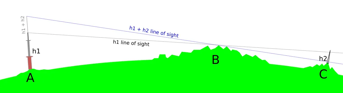
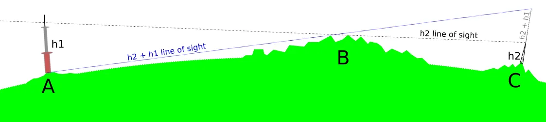
Pic. 2, 3. The manual approaches to the line of sight computation between two artificial objects, where: A – Tower 1 location; B – High mountain range; C – Tower 2 location; h1 – Height of tower 1; h2 – Height of tower 2.
Since we have tower 1 located at the top of the small hill A, the visual range from its top could advance the tower 2 located at the top of mountain C located beyond the big mountain range B, assuming that it’s not forested at all and neglecting the Earth curvature. In this case, an observer sitting at the very top of tower 1 (and optionally tied up by twine or chain) would be able to see just the top of tower 2, although the vertical difference between the top of tower 2 and the total range of visibility from tower 1 would be quite enough to make this object distinguishable above the mountainous horizon. If, for instance, the very first pattern (Pic.1) would show the lines of sights roughly between the tops of these towers, then it could be merged with mountainous horizon B, making both of them finally not visible to each other. The actual pattern of these lines of sight gives a margin of visibility to these 2 towers between the high mountain range in area B.
Before we convert this understanding into real DEM computations, we should figure out, what should we do by making area C visible from tower 1, if tower 2 doesn’t exist at all.
Usually, we know the height of two structures, so the challenge is straightforward. We should add one height to another, and the result will equal the line of sight between the tops of these structures. This is the simplest manual method to gauge the potential visibility between two artificial objects.
Imagine, that the height of tower 1 is 250m and the height of tower 2 is 125m.
If we add the height of tower 2 to the height of tower 1, as presented in the pattern above (Pic. 2), we should be able to reach horizon C since the Earth’s curvature is not taken into account seriously. The next pattern (Pic. 3) shows the opposite way.
In our first case, the following equation 250m+125m = 375m means, that if tower 1 would reach 375m altitude, then the ground, where tower 2 stands could become visible to an observer. As we have considered the margin of visibility for two lines of sight considered in the very first pattern (Pic. 1), this situation could obviously happen at a bit lower altitude.
Looking at it from the opposite place, place C, the equation could look like this: 125m+250m = 375m, which would give exactly the same result with regard to tower 1. The observer elevated 375m above place C would be able to see the grounds of place A and vice versa.
Regarding the viewshed computations, based on DEM, the discussed equations will be valid strictly only between one construction and another. It’s pointless to use these assumptions in different directions, as objects like those considered might not exist at all or have completely different altitudes if they do so.
3. USING HEYWHATSTHAT.COM FOR LINE OF SIGHT COMPUTATION BETWEEN TWO ARTIFICIAL OBJECTS – CASE STUDIES – METHOD I
For the purpose of this writing, the Heywhatsthat.com service seems to be the best, because unlike others it calculates the visibility cloak on the map and gives an option for analyzing the geometry of the line of sight.
CASE I: SUCHA GÓRA TV TOWER – KRAL’OVA HOL’A TV TOWER – 155KM
A. BRIEF DESCRIPTION
The Sucha Góra TV Tower is located in my Polish homeland. It has been maintained recently, which resulted in the increment of its total height from 116,5m to about 147m. The construction is located at the top of Sucha Góra (pron. Soohah Goorah /en. The Dry Mountain) rising 585m.a.s.l. on the Dynowskie Foothills in Carpathian Mts.
The Kral’ova Hol’a TV Tower is located at the easternmost edge of the Low Tatras range in Slovakia. The 137,5m transmitter stands at the top of Kral’ova Hol’a (pron. Kralovah Hallah/ en. The King’s Hall) counting roughly 1946m.a.s.l.
B. COMPUTATIONS
TaV - total altitude of visibility
h1a - height of Sucha Góra Mt - 585m.a.s.l.
h1b - height of Sucha Góra TV Tower - 147m.a.g.l.
h2b - height of Kral'ova Hol'a TV Tower - 137m.a.g.l. (altitude rounded down)
hf - height of forest - 35m
vm - visual margin of visibility - 25m
Tvm - total margin of visibility
Tvm = hf+vm

TaV = (h1a + h1b + h2b) - (hf + vm) /OR/ TaV = (h1a + h1b + h2b) - Tvm
TaV = (585+147+137)-(35+25)
TaV = (585+284)-60
TaV = 869-60
TaV = 809
We are assuming the visibility from 809m.a.s.l. then, or alternatively from 224m.a.g.l (284-60 = 224) (Pic. 4).
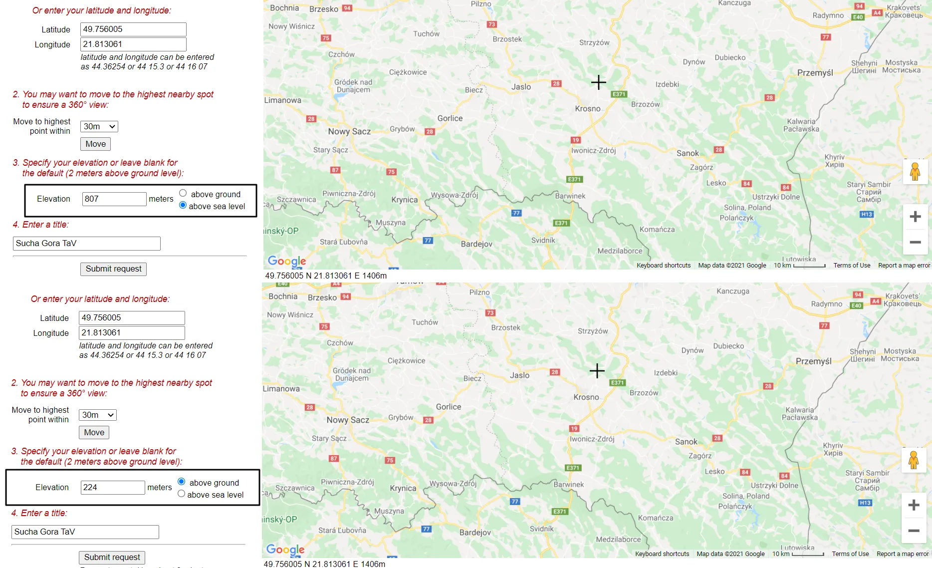
Pic. 4 Two ways of the elevated line of sight computations: absolute – from the sea level and relative from the altitude of the local ground.
C. RESULTS
As per the captures below, the Kral’ova Hol’a TV tower is not visible from the top of Sucha Góra TV tower (Pic. 5,6).
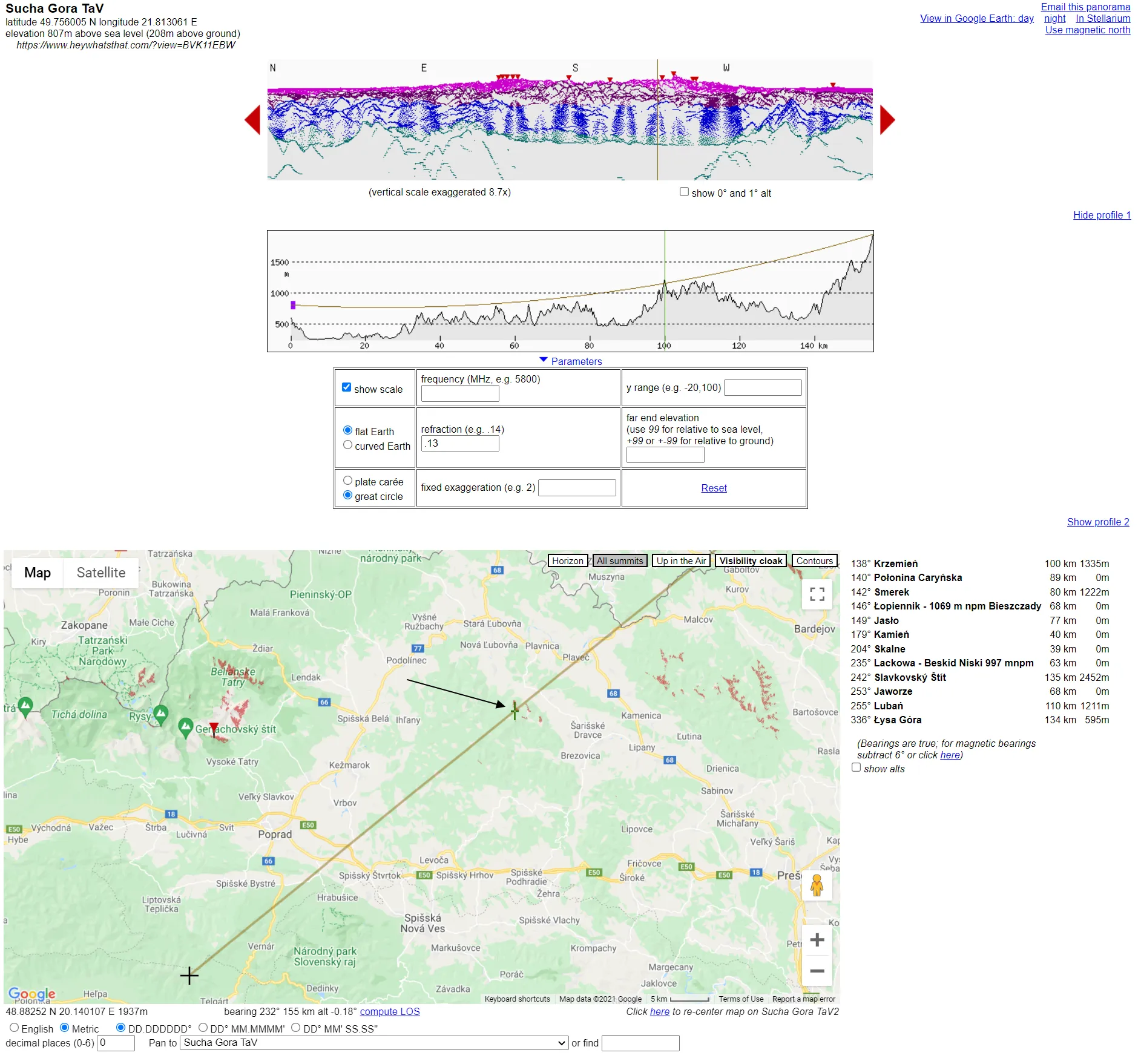
Pic. 5 The Case I visibility computations. The Kral’ova Hol’a TV Tower remains invisible from Sucha Góra TV Tower under standard refraction coefficient, because of the Lewockie Hills. Click to enlarge.
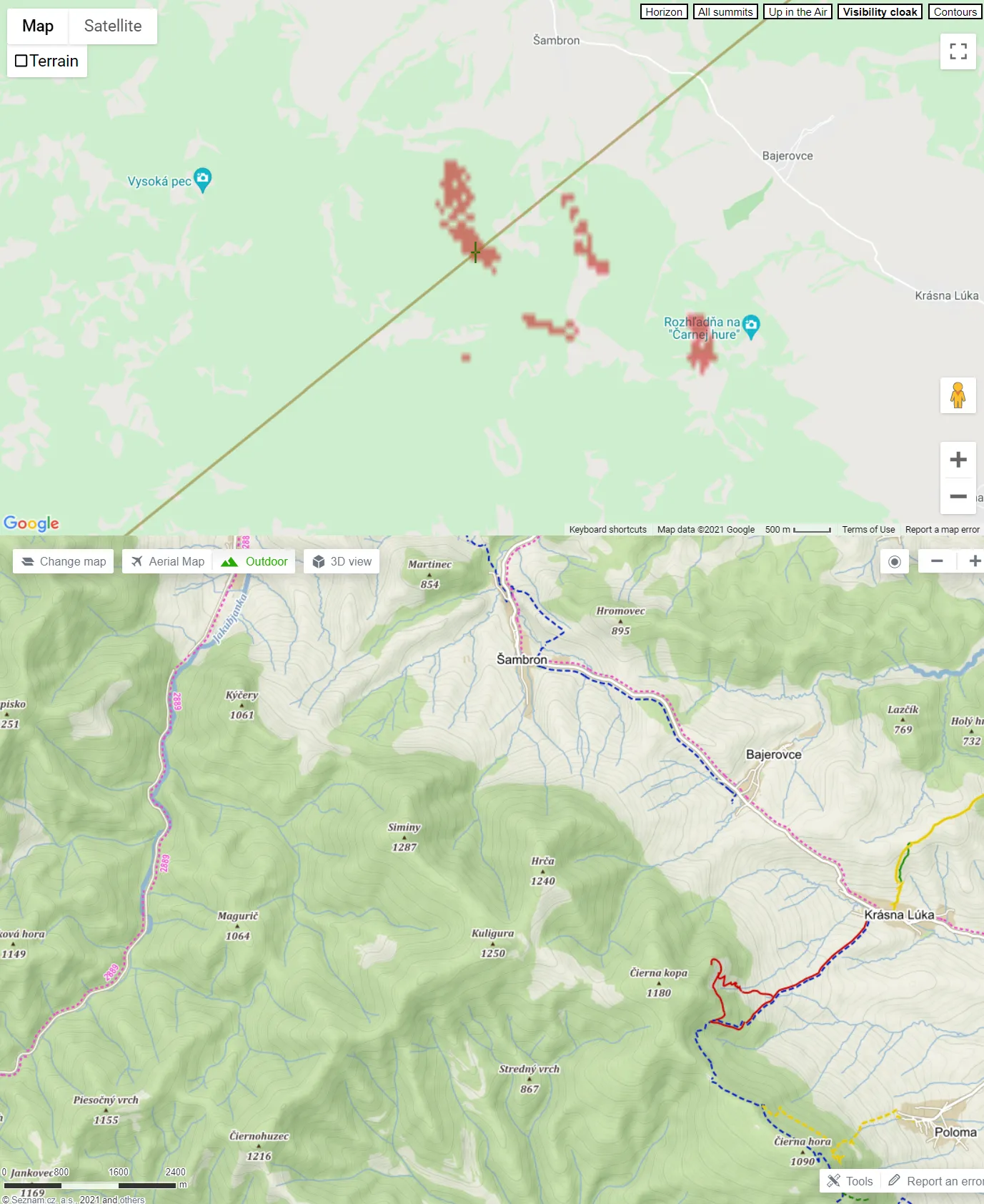
Pic. 6 Detailed views at the Lewockie Hills, which make the visibility barrier between the Sucha Góra TV tower and Kral’ova Hol’a TV tower (Mapy.cz).
In order to confirm our results, we can do the same in the reverse direction.
The formula will look like this:
h2a - height of Kral'ova Hol'a peak
h2b - height of Kral'ova Hol'a TV Tower
h1b - height of Sucha Góra TV Tower
Tvm - total margin of visibility (as discussed earlier)

TaV = (h2a+h2b+h1b)-Tvm
TaV = (1946+137+147)-60
TaV = (1946+284)-60
TaV = 2230-60 = 2170m.a.s.l.
and the Heywhatsthat.com preview accordingly:
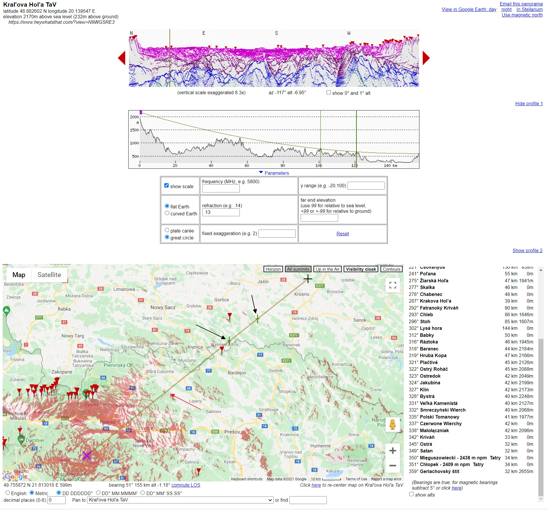
Pic. 7 The case I visibility computations in the reverse direction. Sucha Góra TV Tower remains invisible from the top of Kral’ova Hol’a TV tower because of Hanczowskie Mts and Magura Wątkowska’s hills in the Low Beskid range( black arrows) compared to the Lewockie Hills, which are cutting the line of sight from Sucha Góra TV tower (red arrow). Click to enlarge.
which shows completely different hills cutting the analyzed line of sight. The reason behind it is the Earth’s curvature, which detailed computation has been neglected in this article, as I base it on Heywhatsthat.com only. It will be a separate topic about it in the future. However, If you wish to get deeper into these calculations, you can try the following formula:
d = 3,854 * (√h1 +√h2) [km] (distances in meters)
d = 121,91 * (√h1 +√h2) [km] (distances in kilometers)

where:
d = distance
h1 - height of object 1
h2 - height of object 2
which is the basic one for the Earth’s curvature calculation.
I think I could bring another reason here, which is the discrepancy between these 2 profiles marked in the opposite direction. As the second method confirms (Pic. 14), the first line of sight profile between Sucha Góra TV Tower and Kral’ova Hol’a TV Tower could be set a bit inaccurately.
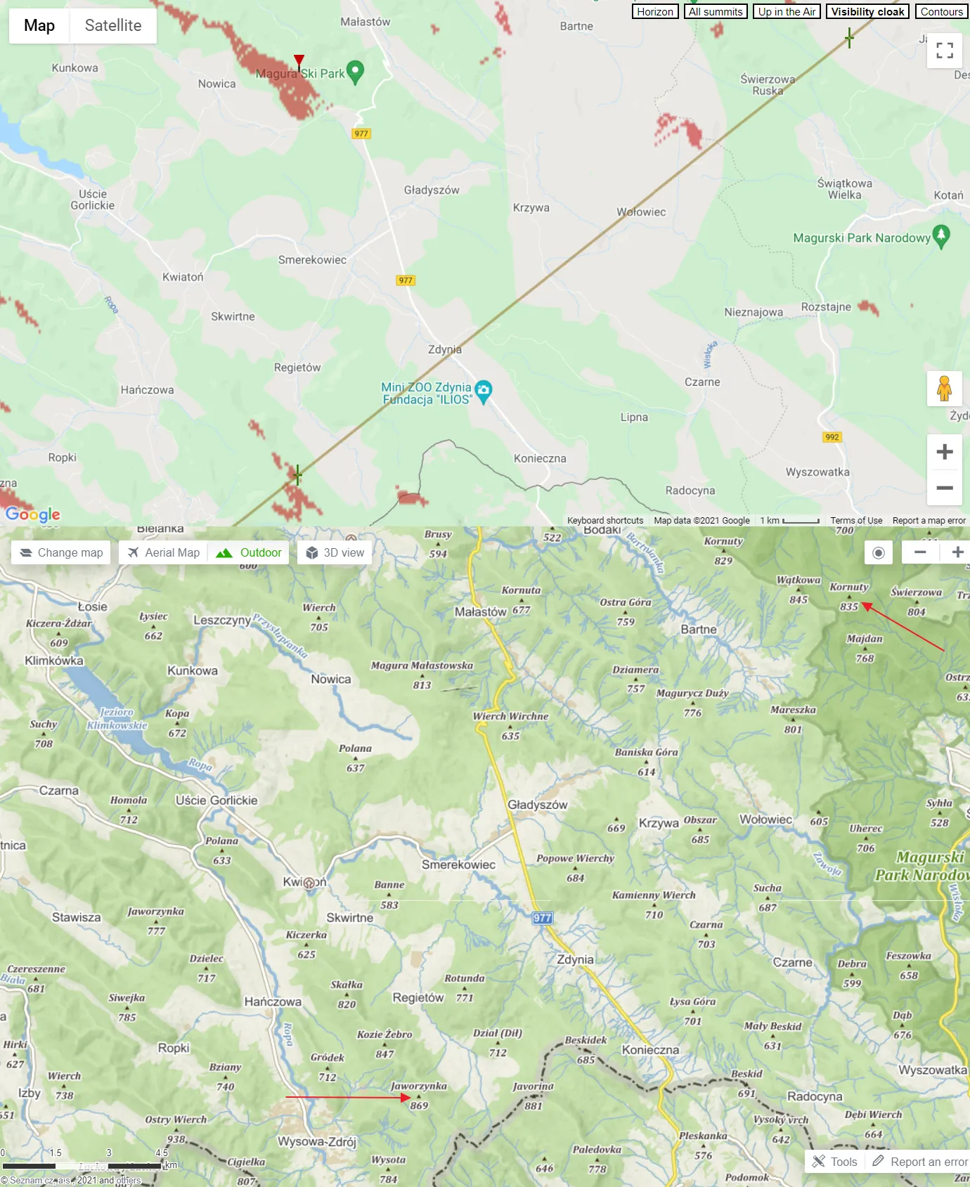
Pic. 8 Detailed views of the Low Beskid range, in which some hills cut down the visibility of Sucha Góra TV Tower from Kral’ova Hol’a TV Tower (mapy.cz).
CASE II: BIRMINGHAM TV TOWER- STOKENCHURCH BT TOWER – 115KM
A. DESCRIPTION
Birmingham BT Tower is situated just north of the city center. It’s the tallest construction in the city rising at 152m.a.g.l.
Stokenchurch BT Tower it’s a reinforced concrete object built at Chiltern Hills, which has a 99m altitude above the ground. The object is situated next to the M40 motorway between London and Oxford.
B. COMPUTATION
h1b - the height of the Birmingham BT Tower
h2b - the height of the Stokenchurch BT Tower
Tvm - total margin of visibility

TaV = (h1b+h2b) - Tvm
TaV = (152+99) - 60
TaV = 251-60 = 191m.a.g.l.
This time I’ve used the shorter computation because I am not sure about the height of the ground, where the Birmingham BT Tower stands. As was covered above, we can use the “Meters above the ground” option in the Heywhatsthat.com service (Pic. 4).
C. RESULTS
These towers are invisible to each other, as per the estimations shown below (Pic. 9, 10).

Pic. 10 Case II of visibility computations between Birmingham BT Tower and Stokenchurch BT Tower blocked by Cotswolds hills.
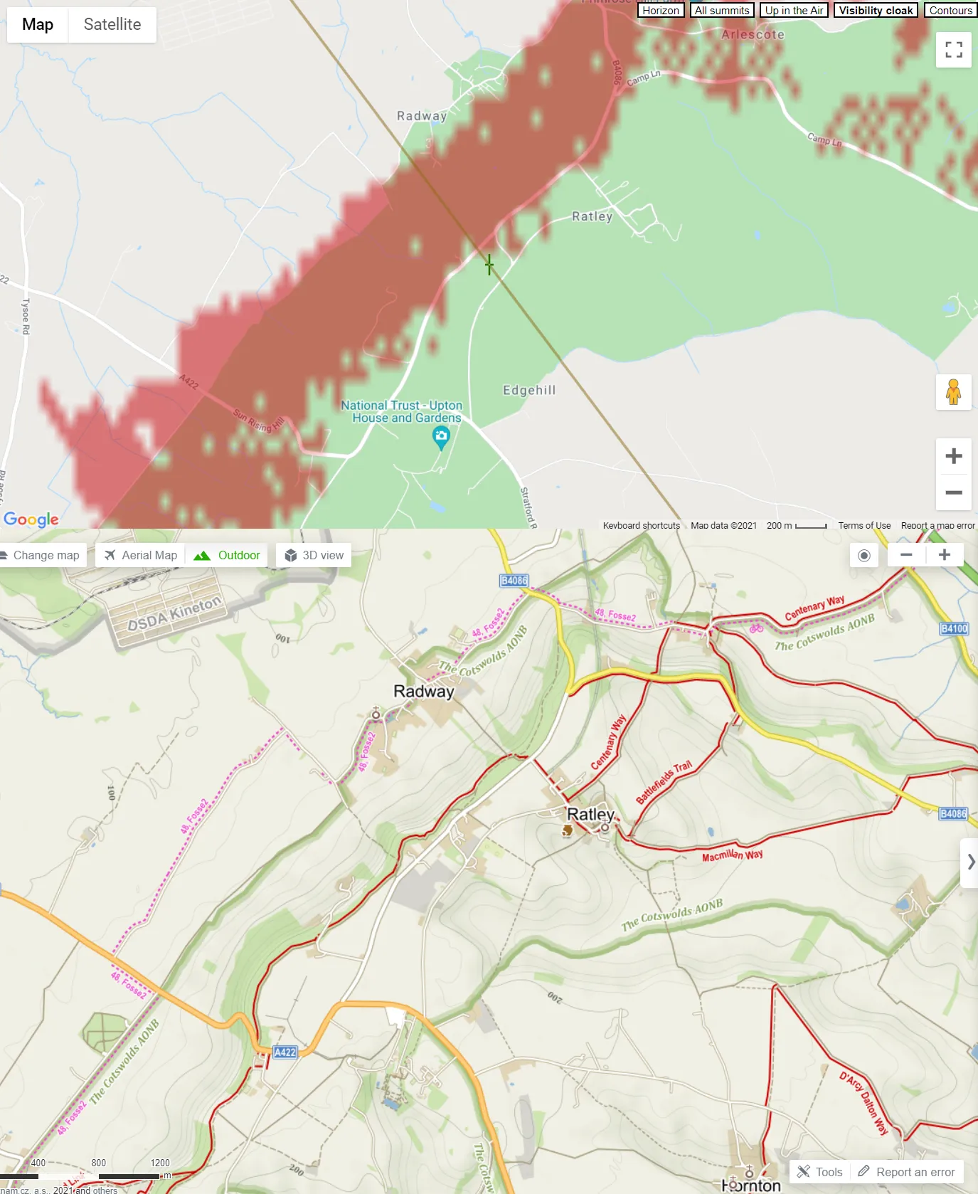
Pic. 11 Detailed views at Cotswolds Hill, which breaks the line of sight between the Birmingham BT Tower and Stokenchurch BT Tower (Mapy.cz).
Let’s have a look also from the opposite direction…
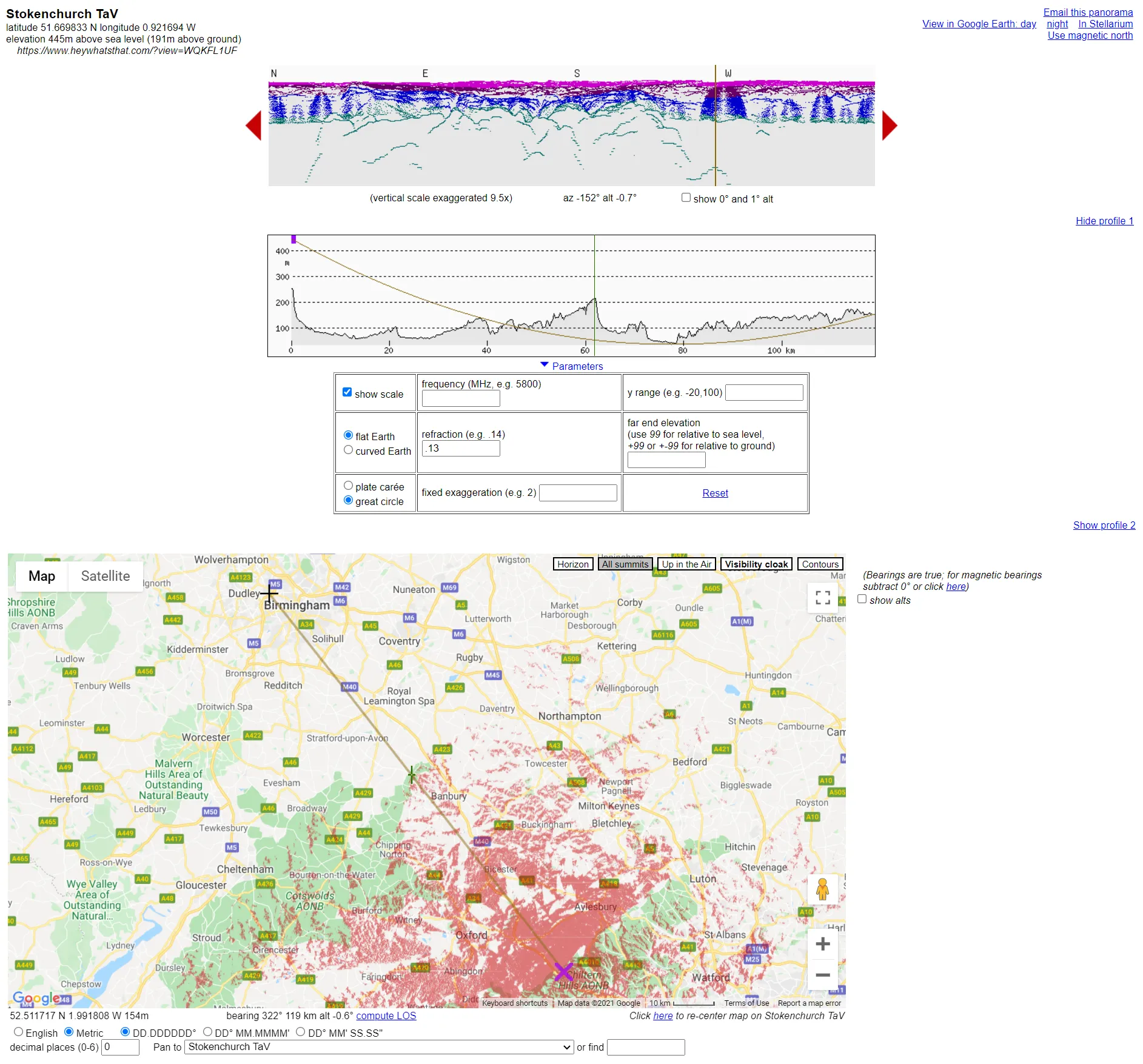
Pic. 12 Case II of visibility computations between Stokenchurch BT Tower and Birmingham BT Tower, which cannot see each other because of the Cotswolds hills on the way between them.
CASE III: SANDY HEATH TRANSMITTER – BELMONT TRANSMITTING STATION – 134KM
A. DESCRIPTION
Sandy Heath Transmitter is located near Sandy Town in Bedfordshire, UK. It rises 244m above the ground.
Belmont transmitting station stands in The Wolds – a hilly charming landscape lying next to the North Sea. This is the second tallest structure in the UK, rising 351m above the ground.
B. COMPUTATION
We use the same computation as in Case II because the rough altitude above sea level is not known.
h1b - the height of the Sandy Heath transmitter
h2b - the height of the Belmont transmitting station
Tvm - total margin of visibility

TaV = (h1b+h2b) - Tvm
TaV = (244+351) - 60
TaV = 595-60 = 535m.a.g.l.
C. RESULTS
In this case, both constructions are intervisible. The line of sight nearly grazes the ground in places (Pic. 13), but if it happens for the circumstances including the margin of visibility, it means, that another 25m of the remaining tower should be visible.
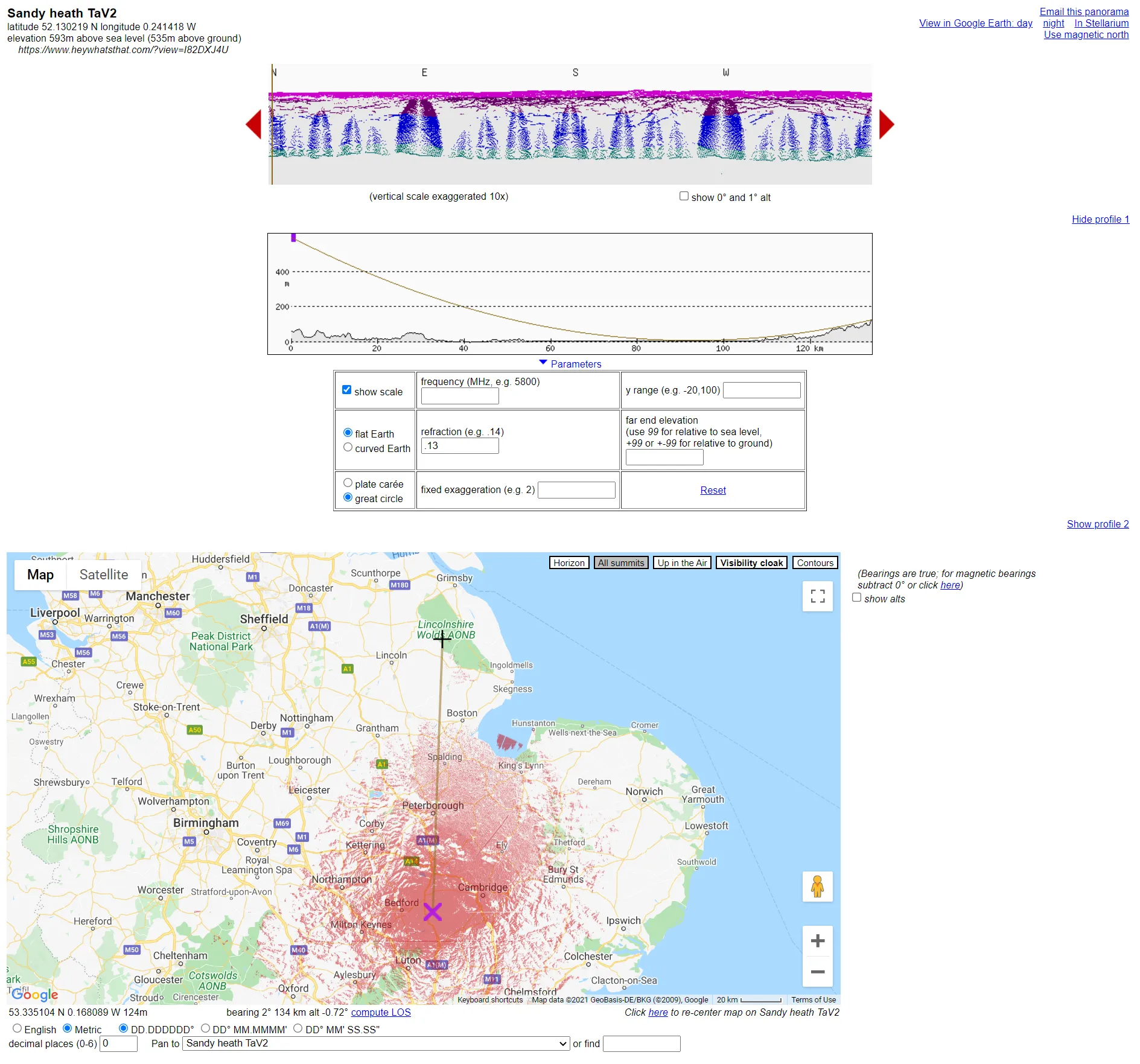
Pic. 13 case III of visibility computations between the Sandy Heath transmitter and Belmont transmitter station.
4. USING HEYWHATSTHAT.COM FOR LINE OF SIGHT COMPUTATION BETWEEN TWO ARTIFICIAL OBJECTS – CASE STUDIES – METHOD II
The second method is based on the visibility cloak, which comes from the altitude of the given artificial object. By computation visibility cloaks for two artificial objects, we can next check the viewshed range for them. If these viewsheds overlap each other, then the tops of these structures are intervisible. Let’s check it through all the cases discussed. You don’t need any formulas here, as the Heywhatsthat.com service does everything for you. On the other hand, you should take care a bit about the performance of these results. They were discussed already for Google Earth, but going a step further, you can always display them a bit smarter, without the satellite imagery. A quite good way to do it can be QGIS or Google MyMaps, where you can upload extracted .kml files (visibility cloak.kml) and display them on Google Maps or OpenStreetMap canvas. Furthermore, in QGIS you can convert them to polygons and extract roughly which part overlaps if it exists at all.
CASE I – SUCHA GÓRA TV TOWER – KRAL’OVA HOL’A TV TOWER – 155KM
As estimated in the first method, the primary hill, which breaks down the line of sight between these two towers is Jaworzynka in Low Beskids (Pic. 7, 14). It’s worth mentioning, that the hills, which straddle these two visibility cloaks advance the Lewockie Hills (Pic.5, 14), which explains away the first situation (Pic. 5), where the line of sights terminates in that place. Now, we have proof of the inaccuracy of the very first profile (Pic. 5). It could be the result of parallax against the mountains across the line of sight. Even 200m in a horizontal line can cause the differences such as this.
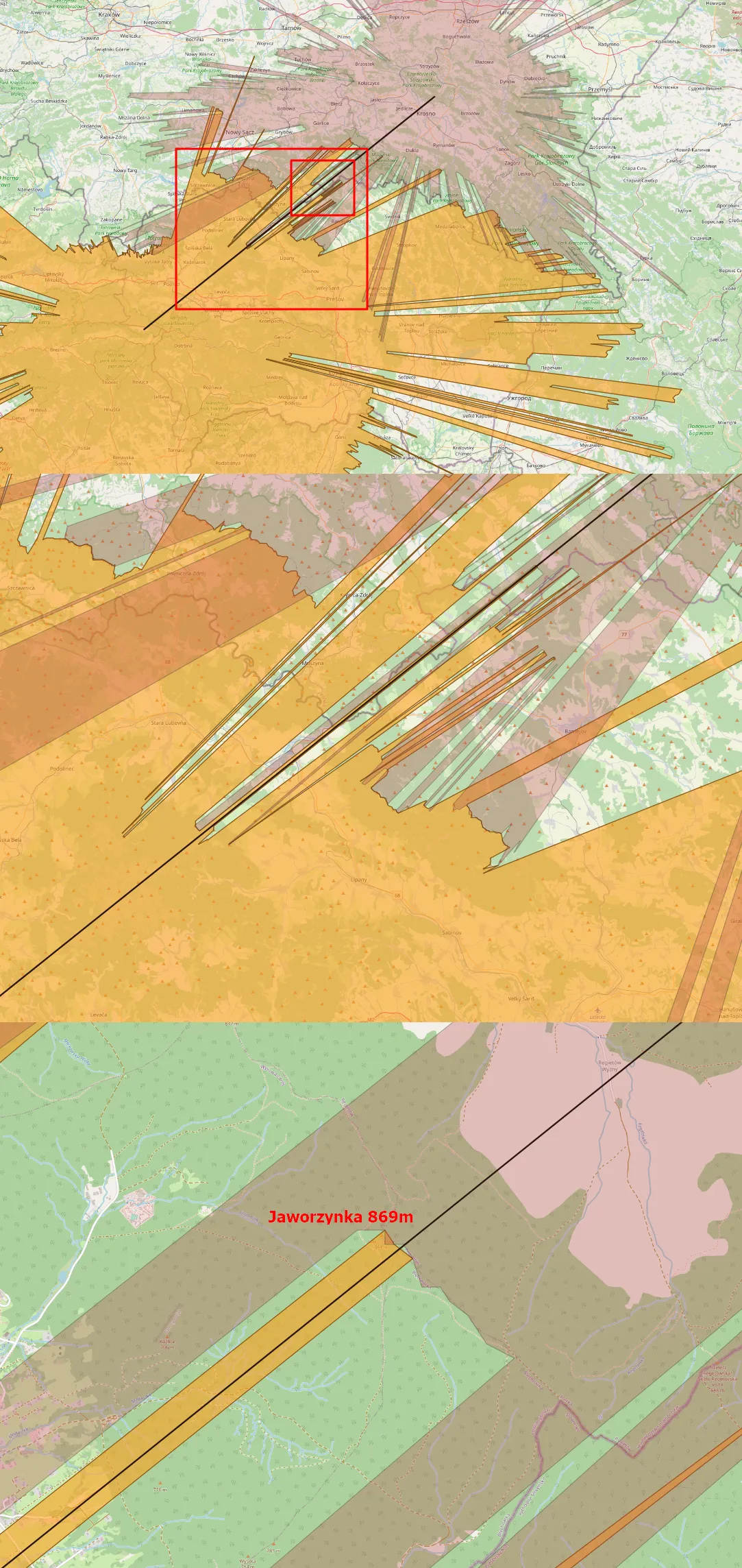
Pic. 14 The visibility cloaks Sucha Góra TV Tower and Kral’ova Hol’a TV Tower.
In both cases the total altitudes of the tower tips have been cut down by 30m (60m in total) due to forests, and so on. Looking at the image above we can clearly see, that both visibility cloaks are quite separated from each other in the line of sight. It definitely excludes the visibility of these 2 objects from each other. Anyhow, if an observer moves just 100m northwest, towards the top of the Jaworzynka Hill, he will see both objects (at least their tips) in opposite directions! In fact, finally, these two towers remain not intervisible! The same applies to the Lewockie Hills, which were meant to be the reason for visibility failure between these two towers. They’re just about 500m from the line of sight. Looking in the opposite direction it’s just 40m! (Pic. 15) Now, you are convinced enough about the high accuracy required for analyses like these!
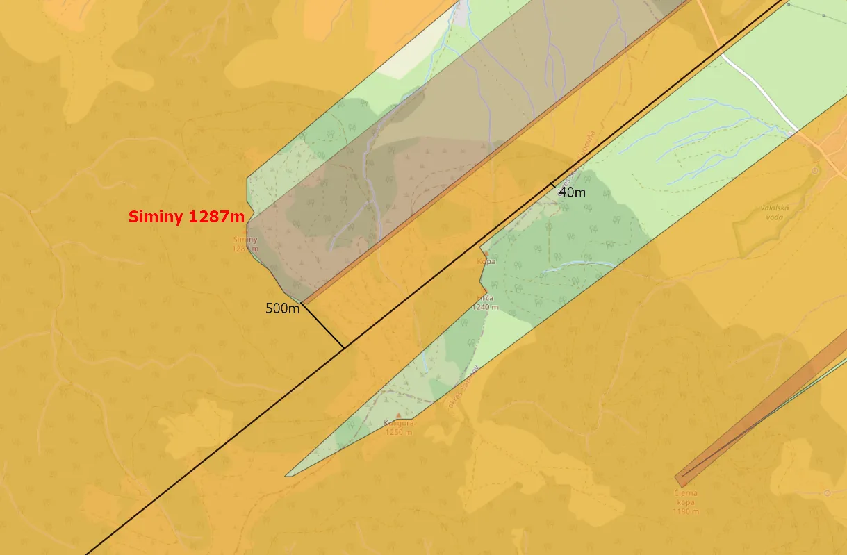
Pic. 15 The narrow part of the viewshed along the line of sight between Kral’ova Hol’a TV Tower and Sucha Góra TV Tower proves, that the accuracy of defining the line of sight profile between two objects is in high demand.
These two towers can be visible when the refraction coefficient exceeds 0.25.
CASE II BIRMINGHAM BT TOWER – STOKENCHURCH BT TOWER – 115KM
This method also proves that these 2 objects cannot see each other. As it was computed previously, the northeasternmost part of Cotswolds Hills interrupts the line of sight completely (Pic. 16). The refraction coefficient of 0.7 is required for making these 2 towers visible, but it’s rather unrealistic. Again, 30m was subtracted from both altitudes.
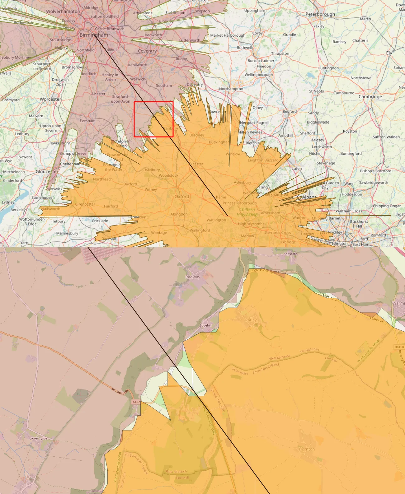
Pic. 16 The visibility cloaks of Birmingham BT Tower and Stokenchurch BT Tower. They are separated from each other along the line of sight, which means that the objects cannot be intervisible.
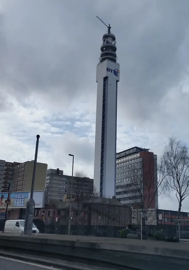
Pic. 17 Birmingham BT Tower as seen from Queensway.
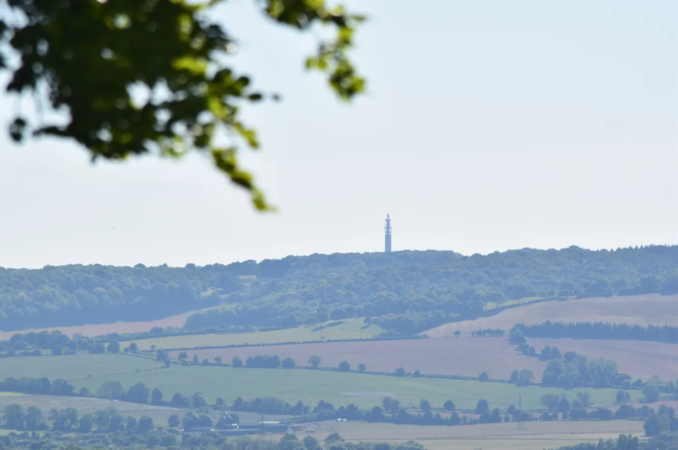
Pic. 18 Stokenchurch BT Tower as seen from around Princes Risborough.
CASE III: SANDY HEATH TRANSMITTER – BELMONT TRANSMITTING STATION – 134KM
This is the only case, where two towers are visible from each other. Despite their altitudes being reduced by 30m for known reasons, an observer sitting at the top of one of them could be theoretically able to see the top of the other one (Pic. 17), although even a 100m shift would exclude this possibility!
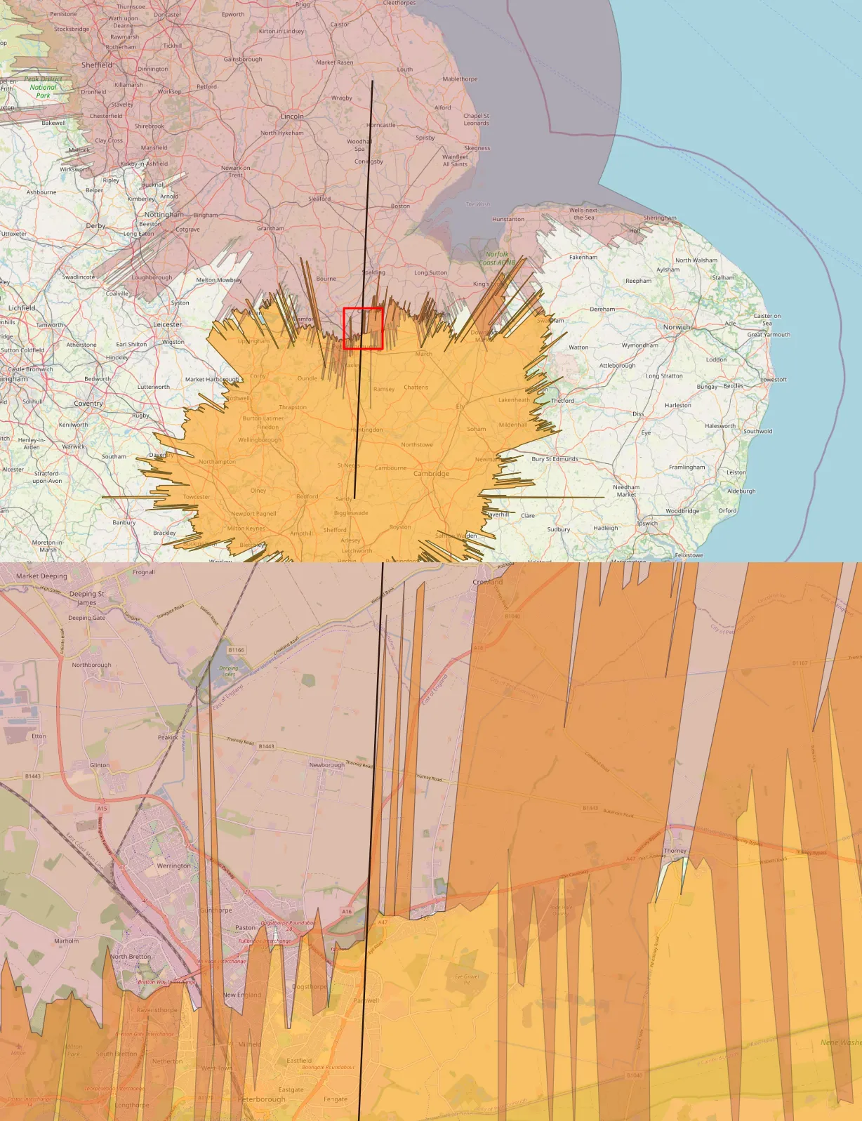
Pic. 17 The visibility cloaks of the Sandy Heath transmitter and Belmont transmitter station, which overlap each other proving that these objects are intervisible.
By concluding this method I would also advise checking, in addition, the area where visibility cloaks overlap. Sometimes, when it happens roughly in some urban areas it might be, that there is some high-rise building located. In turn, even for “positive” results of computation the line of sight will remain obstructed.
Pic. 22 Belmont transmitter station as seen from the Benniworth village.

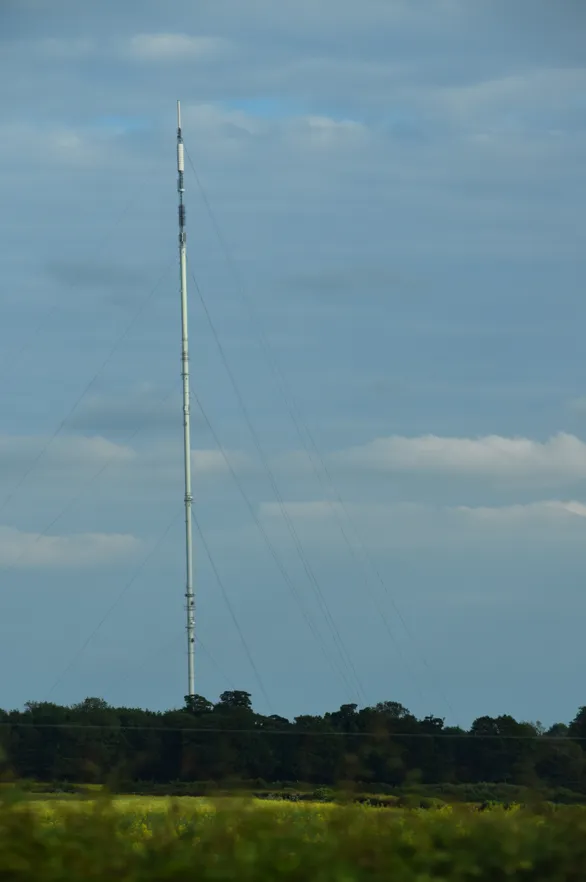
Pic. 23 The close-up view at Sandy Heath transmitter.
5. EXAMPLES
I would like to show you some examples of objects visible from higher parts of another object. One of the best examples is my visit to The Shard in London, where I could watch the horizon from about 270m above the local ground. There were some constructions visible, which wouldn’t be possible to spot from the ground (Pic. 24, 25).

Pic. 24 The former view of the Didcot powerplant chimney rising above Chiltern Hills as seen from The Shard observation deck at a distance of about 80km. This chimney wouldn’t be visible from the ground at that location.
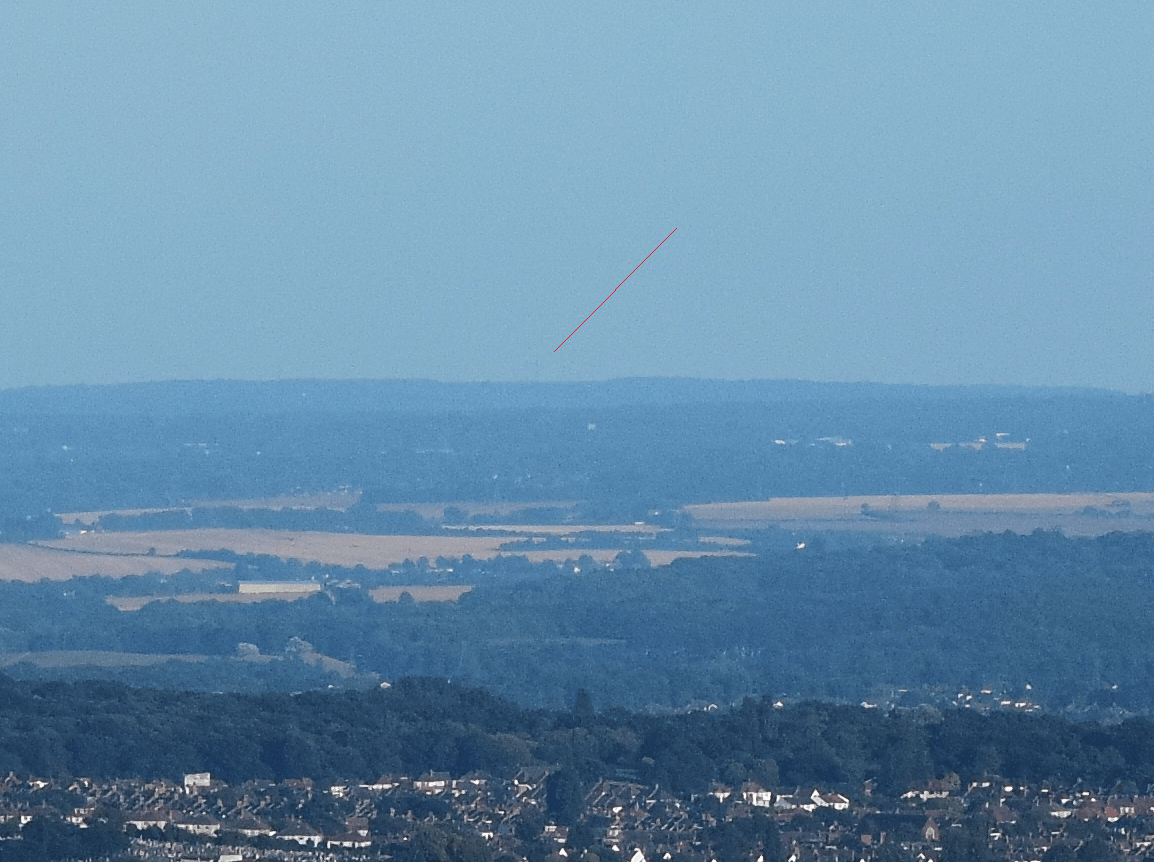
Pic. 25 The view at Dover transmitter from The Shard observation deck. This construction is visible only from an elevated position, which gives the observation deck.
6. SUMMARY
The Heywhatsthat.com service gives a couple of options for estimating the visual range between two artificial objects. By using these computations we don’t need to worry about the calculations of the Earth’s curvature, which this platform takes care of. However, if you wish to have more detailed results, additional calculations are required. For the time being, this article gives you a hint on how to estimate the potential visual range between two objects. The more precise continuation of this matter is planning for the future.
Both methods are different from each other because the first one is based on geometrical interpretation and the second one is focused more on graphic depiction. The case studies reflect three different kinds of topography from the mountainous regions across the highland areas and finally the lowlands with no serious obstruction. In all the cases the altitudes have been reduced by 30m, which corresponds more or less to the height of the trees and forests in general. The output is valid strictly along the marked line of sight only.
This is the first approach for possible viewshed extension in terms of long-distance observations, where we are considering something appearing far away above the horizon instead of in the vicinity, as discussed in terms of the Visual Impact Size (VIS) method. I would like this subject to be developed in the future by expanding it too much more precise calculations and patterns.
Mariusz Krukar
References:
- Caha J., 2017, Representing buildings for visibility analyses in urban spaces, (in:) Dynamics in GIscience, Lecture Notes in Geoinformation
and Cartography, Springer International Publishing - Czynska K., 2018, High precision visibility and dominance analysis of tall building in cityscape, (in:) City Modelling & GIS, vol. 1
- Fisher P.F., 1996, Extending the Applicability of Viewsheds in Landscape Planning, (in:) Photogrammetric Engineering and Remote Sensing, 62(11), pp. 1297-1302
- Pompa-Garcia M., et al., 2010, Viewshed Analysis for Improving the Effectiveness of Watchtowers, in the North of Mexico, (in:) The Open Forest Science Journal, vol.3, p.17-22.
- Popelka S., Vozenilek V., 2010, Landscape visibility analysis and their visualisation, (in:) Dept. of Geoinformatics, Palacky University, Olomouc, Czech Republic, conference paper
- Sander A.H., Manson S., 2007, Heights and locations of artificial structures in viewshed calculation: How close is close enough?, (in:) Landscape and Urban Planning 82(4), 257-270.
Links:
- https://notesfrompoland.com/2021/02/22/warsaw-skyscraper-becomes-eus-tallest-building/
- World’s top 100 tallest buildings
- The Visual Impact Size method explained
- https://landscapearchaeology.org/2019/visual-impact-analysis/
- Snellius vs Pitagoras 1:0 (Polish)
- https://earthcurvature.com/
- Earth curvature – calculation of the height of the obscured part of the structure
Forums:
Wiki:
