A guide for displaying the Sweet Home 3D model in Google Earth
Sweet Home 3D is an open-source architectural design software, mostly dedicated to interiors, which helps users create a 2D plan of a house with a 3D preview. In this design software, a user can also decorate exterior and interior views by placing a multitude of objects. These objects are mostly furniture and home appliances, which have been categorized by sections tailored for a specific room.
The most advantageous feature of this open-source software is creating a virtual environment, which can be eventually used for designing a blueprint of houses. Admittedly, the 3D preview giving a piece of virtual setting is nothing unusual in this type of software environment. The wide spectrum of other applications has the same capability for showing any 2D drawing in 3D. The primary advantage of the Sweet Home 3D above them is its marvelous intuitiveness in use. It means, that anyone can sketch a good-looking hose plan without knowledge of drawing, which is required i.e. for CAD-based applications.
The 3D model displayed in the Sweet Home 3D software may not be enough for users, as they potentially want to have it geolocated and embedded in the real scene. Therefore I am coming out with a solution to make this step successful. The negative side of this solution is to use a third-party application, which in this case is Google Sketchup. On top of that, Google Sketchup is not free. However, you can get over it a bit by using the 30-day trial version or installing older versions for several hours. Another problem is the lack of options for automatic geolocation, which might be the pain, but…not necessarily after reading this article!
1. Our first step is to export the 3D view from the Sweet Home 3D program, which saves the file in the .obj format. We just need to right-click the area with our 3D view and select “Export to OBJ format“.
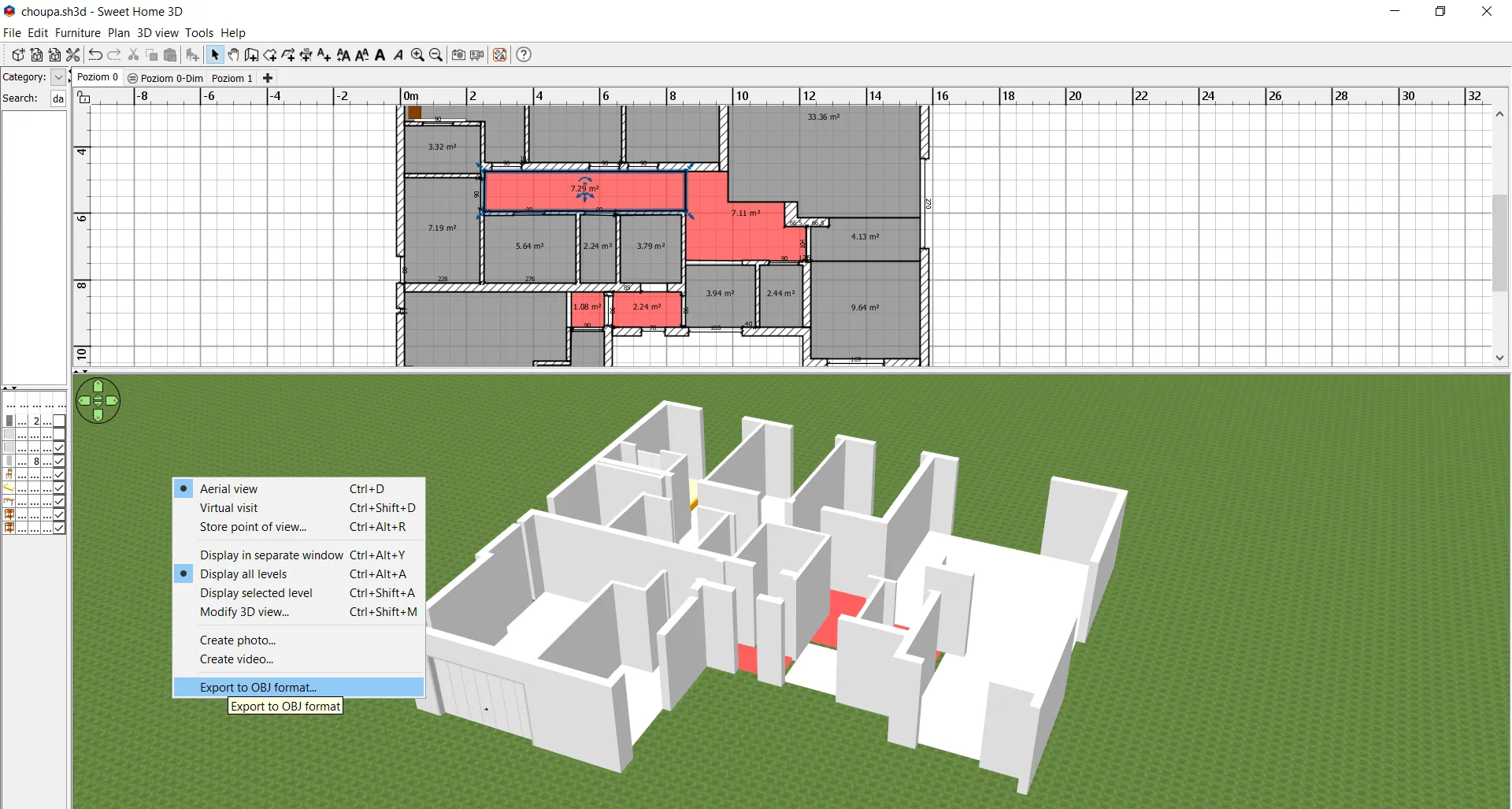
Pic. 1 Export the 3D model from Sweet Home 3D in the .obj format.
2. Now, open Google Sketchup and import your file. I assume, that you already have two extensions: TT_Lib and TT_QuadFaceTool installed. If not, please follow the Youtube footage attached below.
However, in the 2017 version, all the extensions are placed in the “Extension Manager” section, as per below: (Pic. 2, 3).

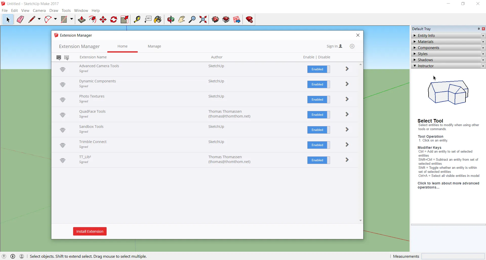
Pic. 2,3 The location of all extensions in Google Sketchup 2017.
When selecting the type of file you want to import, you should click the “Options” which are some things to define at the very beginning (Pic. 4).
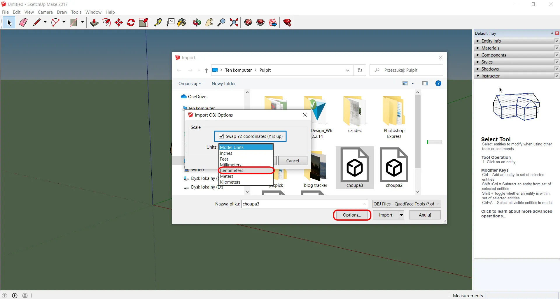
Pic. 4 Import the .obj file to Google Sketchup. By clicking “Options” we can set the measurement units as well as the position of our coordinate system.
This is an important matter because by leaving the default measurements in inches (Model Units) we will have our object enlarged by 2.54! Bear in mind this thing. Selection of the metric values at the very beginning will prevent you from additional and unnecessary size conversions later.
Alternatively, but BEFORE importing your file, you should choose the “Window” from the main toolbar, then “Model Info” -> “Units” and change them from “Architectural” to “Decimal” and pick up the “Centimeters” at the end. Next, you can simply import your .obj file without entering “Options” (Pic. 5).
The other thing is “Swap YZ Coordinates“, which should remain selected as default. If you deselect it at some point, your object will stand vertically.
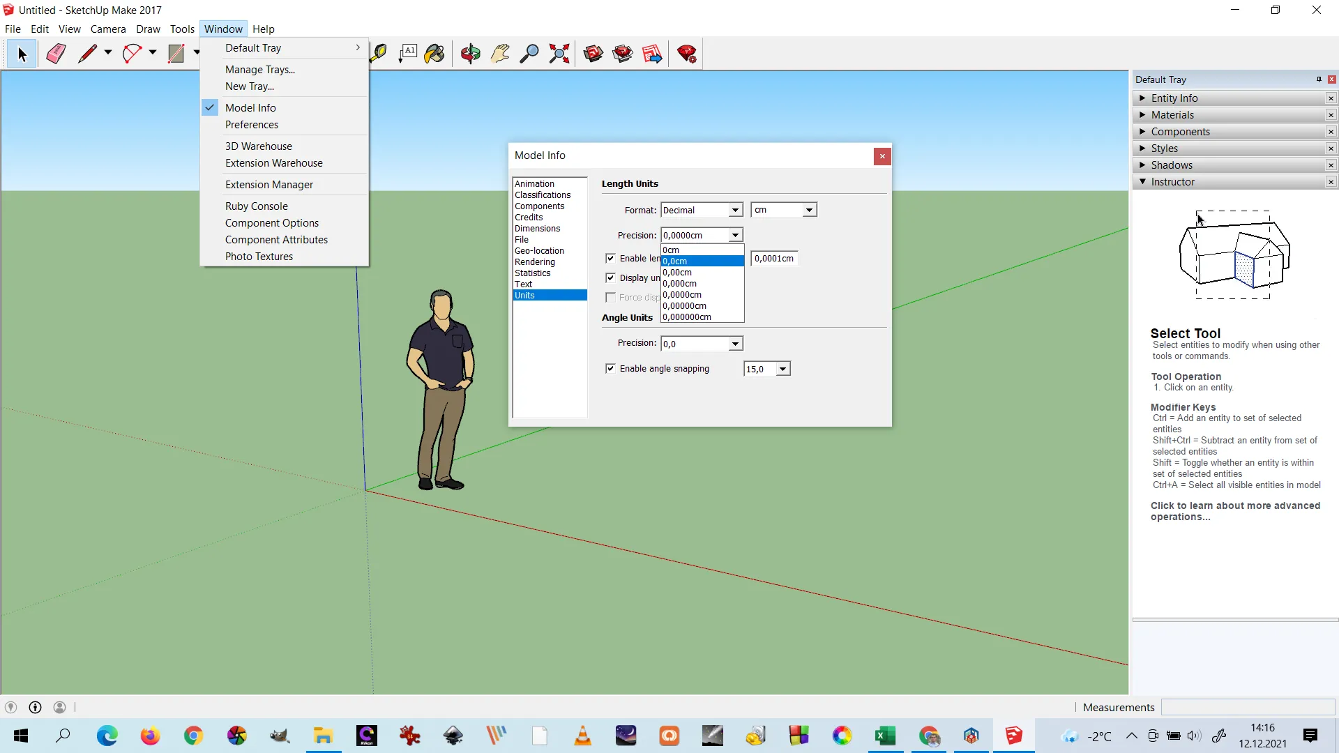
Pic. 5 Google Sketchup ->Window -> Model Info -> changing units before our object is imported!
Thereafter we can preferably set the number of decimals, as shown in the image above, but it’s not necessary.
3. The first thing after importing our file should be the deletion of the person, which always in the blank Sketchup project. You can do it easily by selecting it and hitting the “Del” button (Pic. 6, 7). Alternatively, you can use the “Erase” tool for this purpose.

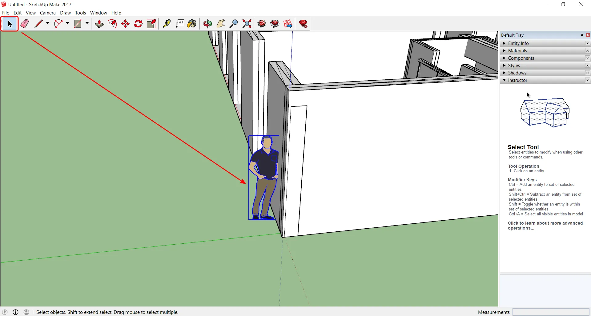
Pic. 6, 7 Deleting the pegman in Google Sketchup by selecting the cursor on our main panel, afterward selecting the object and hitting the “Del” button.
4. Next thing – defining the cardinal points. In Google Sketchup, we have 3 axes: XYZ. As the Y-axis shows up, being swapped with the Z-axis, we should have a different orientation of the whole Cartesian System, as it is rotated along the X-axis. In turn, our X-axis (red) will indicate East, Y-axis (blue) will go to the top and Z-axis (green) will point in the north direction (Pic. 8 – 10).


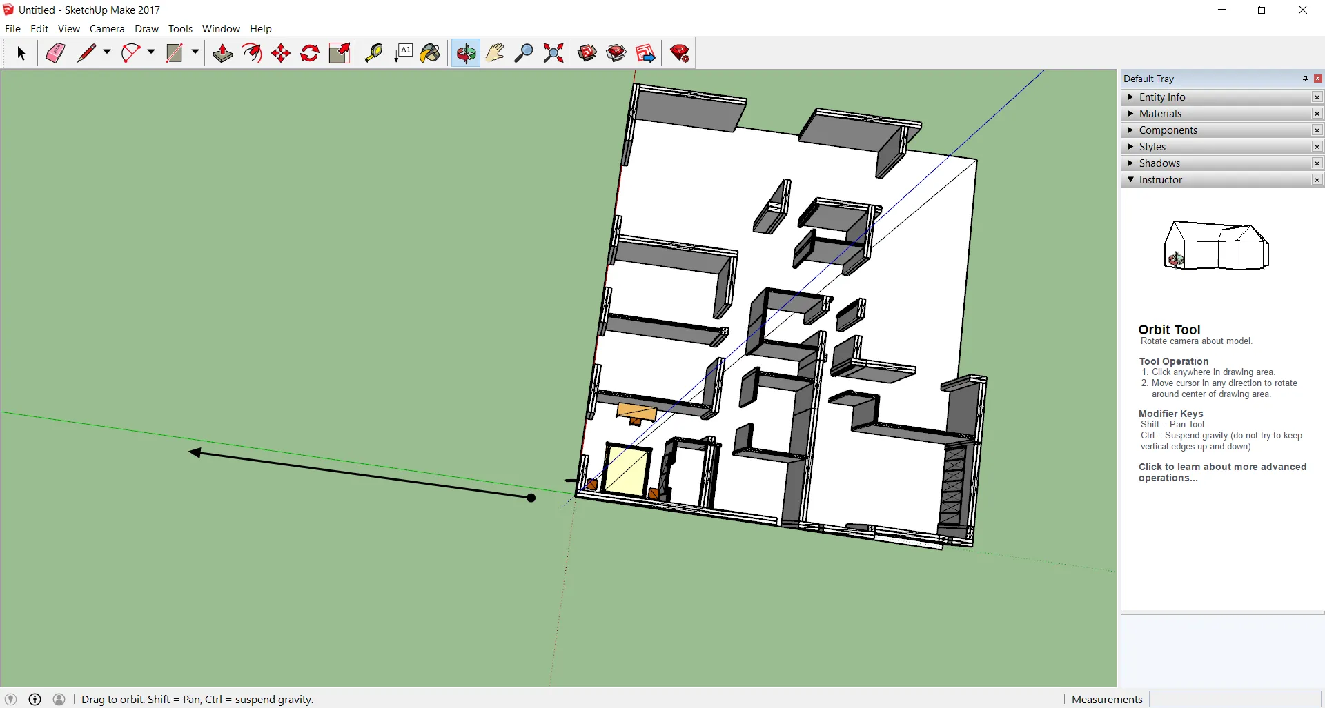
Pic. 8 – 10 Defining the north direction in Google Sketchup which due to swapping Y and Z axes is now indicated by the Z-axis marked green.
5. Now, we should check the location of our building in reality. The example shown above has the garage door oriented roughly towards NW. In Sketchup, according to the default position, they head exactly south. In this case, we should rotate them at least 90° to the left. The first thing we should do here is to check the real building location against i.e. the nearest road. In the case of the example shown, the garage door should be a front of the road. You can check the exact location circumstances both on Google Maps and Google Earth. Next, you should measure the orientation angle of the nearest feature, which in my case is the road mentioned above. The easiest way to do it quickly is:
- run the Windows 10 Snip & Sketch tool by holding: WINDOWS + SHIFT + S buttons simultaneously.
- make the screenshot of your Google Map (preferably by the Box selection),
- toggle the “Ruler” feature from the main toolbar, which includes an embedded protractor in the middle (Pic. 11).
Afterward, you can place the protractor roughly in the location of your object (precisely check the orientation of the nearest feature) and calculate the angles, which are separated by 15° roughly (Pic. 11).
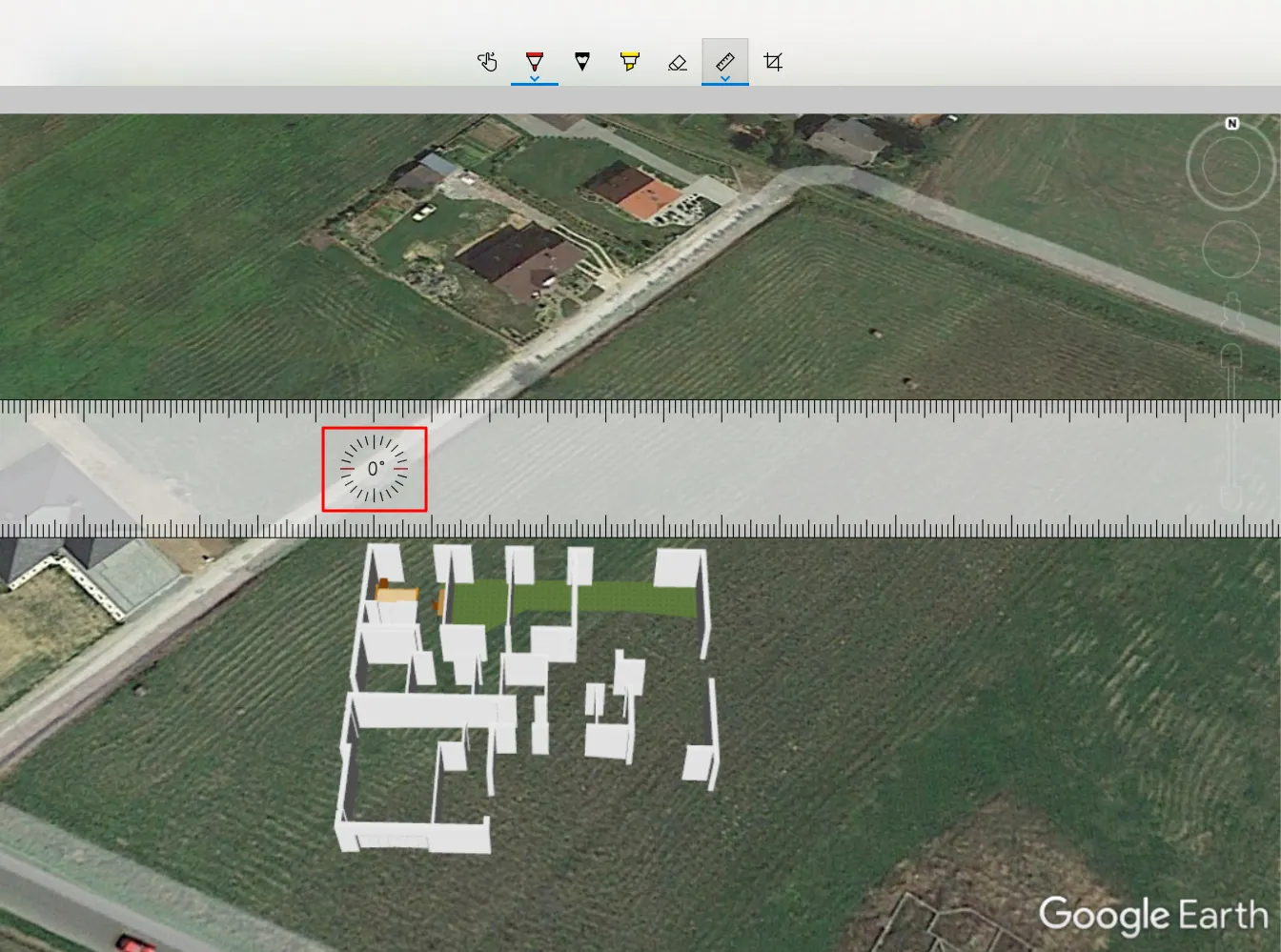
Pic. 11 Measuring the orientation angle of the road by counting it roughly from the North direction.
By looking at this road, where the protractor tool has been placed, we can see, that it goes from about the SW direction to the NE direction at azimuth around 45°. Next, we can add this 45 ° to another 90° which requires additional rotation of our garage door from the south to the west direction. Finally, they must be vis-a-vis the road and, therefore head NW.
6. Since we know the location of our building against local area circumstances, we can rotate it gently in Google Sketchup. The task is quite straightforward, but you must remember some basic rules mentioned in the tutorial below.
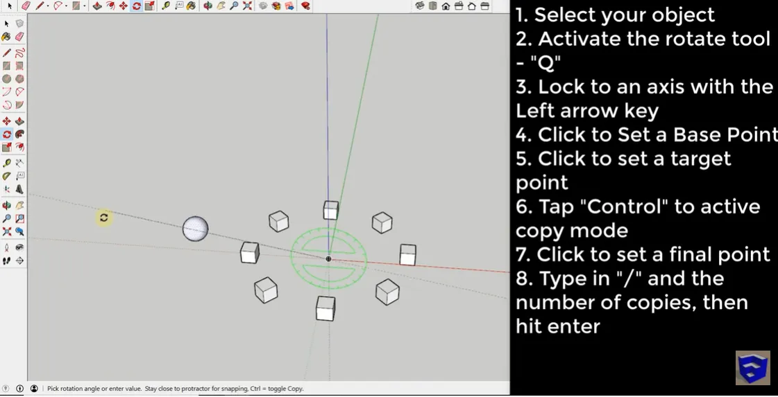
Pic. 10 The basic rules for rotation of an object in Google Sketchup (Youtube.com/TheSketchupEssentials).
Once you get it, please rotate the object gently and look at the “Angle” box in the bottom right at once. You will stop the rotation when the value there hits 135° (Pic. 12).
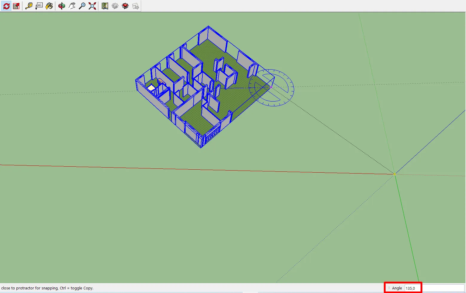
Pic. 12 Rotation of our feature in Google SketchUp with looking at the rotation value simultaneously.
7. After rotation of our object, we can spot, that it’s now quite far away from the place where all the axes cross each other (Pic. 12). In the practical sense, the point where all these axes meet each other corresponds exactly to our further object location. Therefore we should do our best to stick our object with the place of axes crossing. I am coming out with two solutions. The first one is simply dragging our object towards this place (Pic. 13).
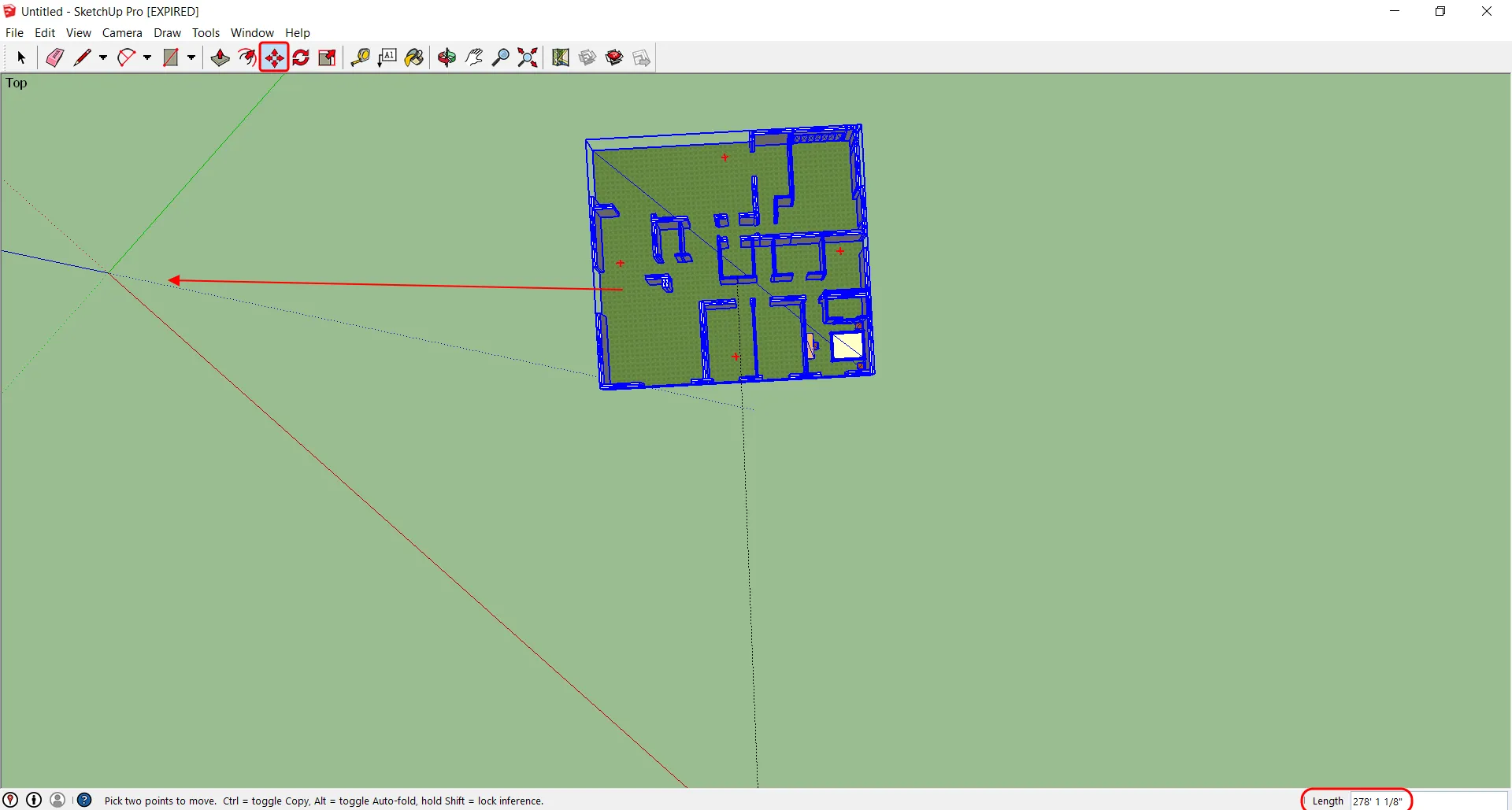
Pic. 13 Moving objects in Google Sketchup.
The second one might be more interesting for you because you can simply adjust the point of access crossing to any part of your building. It sounds amazing, and the details can be seen in the video below.
When you select “Tools” -> “Axes”, just next to your cursor you will see the miniature of the Sketchup axes. By sticking them to the edge of your object you are setting the new point of axes crossing, which will be side by side with your object from now (Pic. 14).
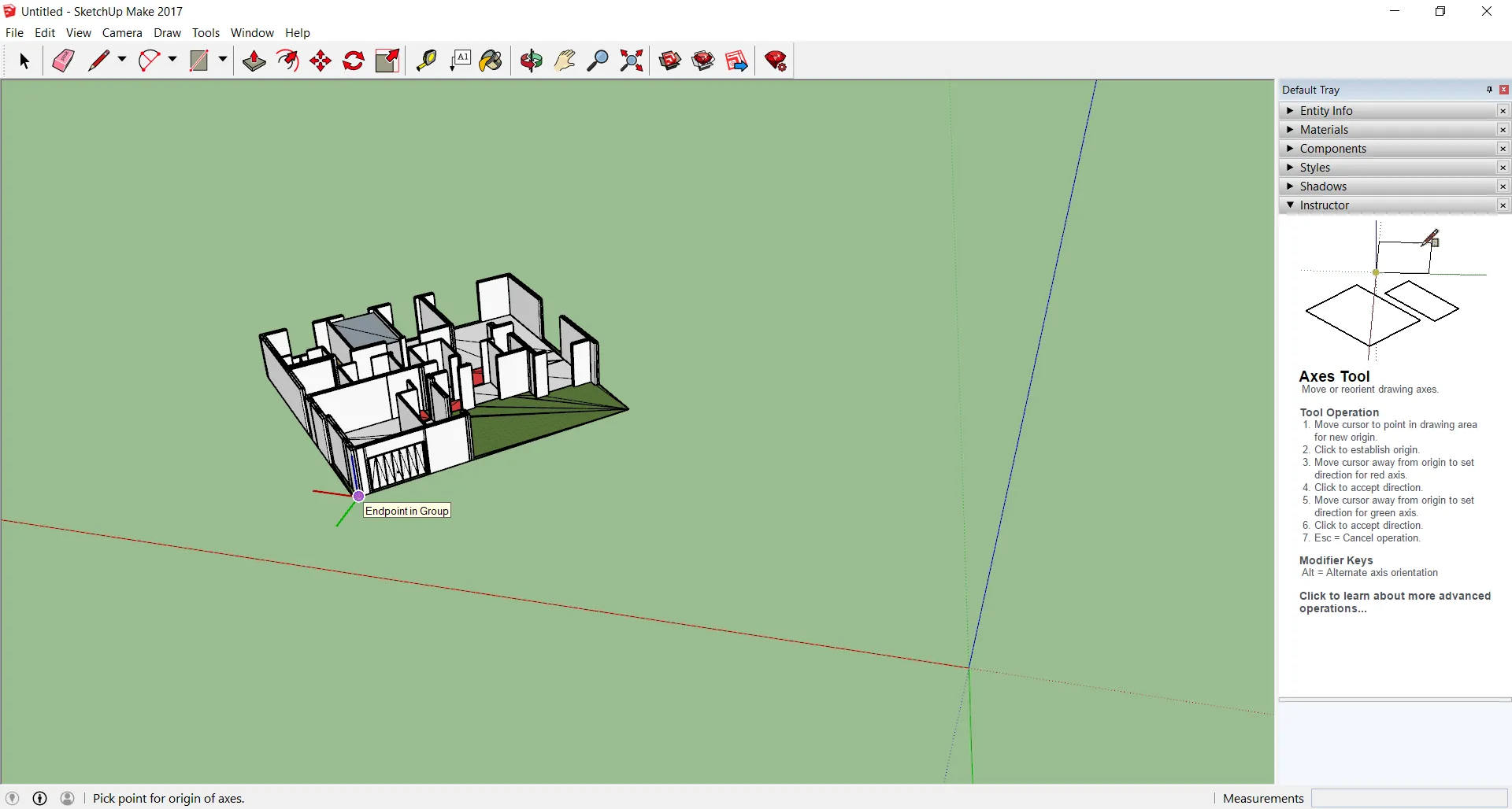
Pic. 14 Setting the new point of axes crossing in Google Sketchup, which becomes sticky with an edge of our object from now.
8. The last thing before export is the geolocation of your object. If you have the Pro version or an account in Trimble, the previous two steps won’t be as complicated as described above. You can geolocate your object automatically and adjust its orientation as per the map overlay underneath.
However, if your situation is the same as mine, and you have neither a pro version nor an account, then the only way to get our building located properly is using the manual way, which remains fortunately available so far.
You should go to the “Window” option in the main bar and select “Model info” -> “Geolocation“, where you should set the coordinates properly (Pic. 15).
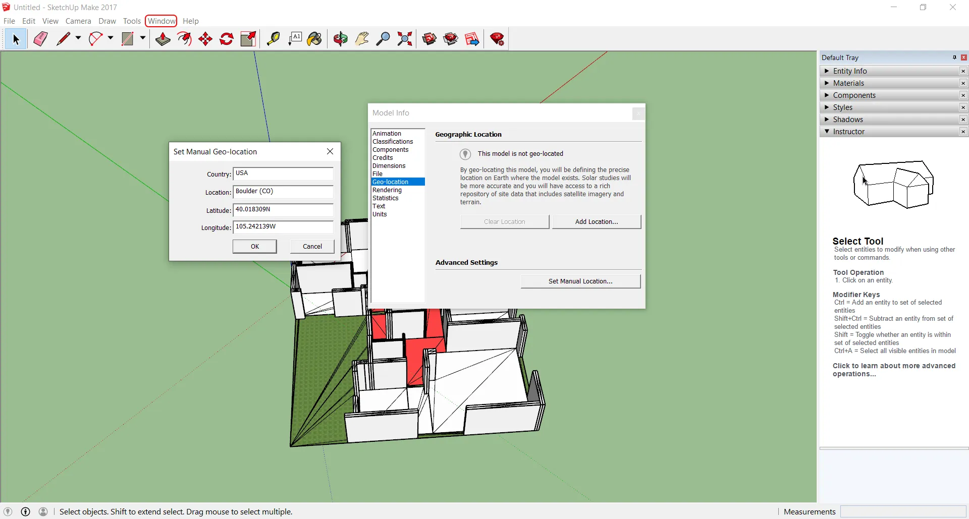
Pic. 15 Setting the location manually in Google Sketchup.
The best way to do it is to get the coordinates from Google Maps by right-clicking on a certain place and copying the first line to the clipboard as shown below (Pic. 16).
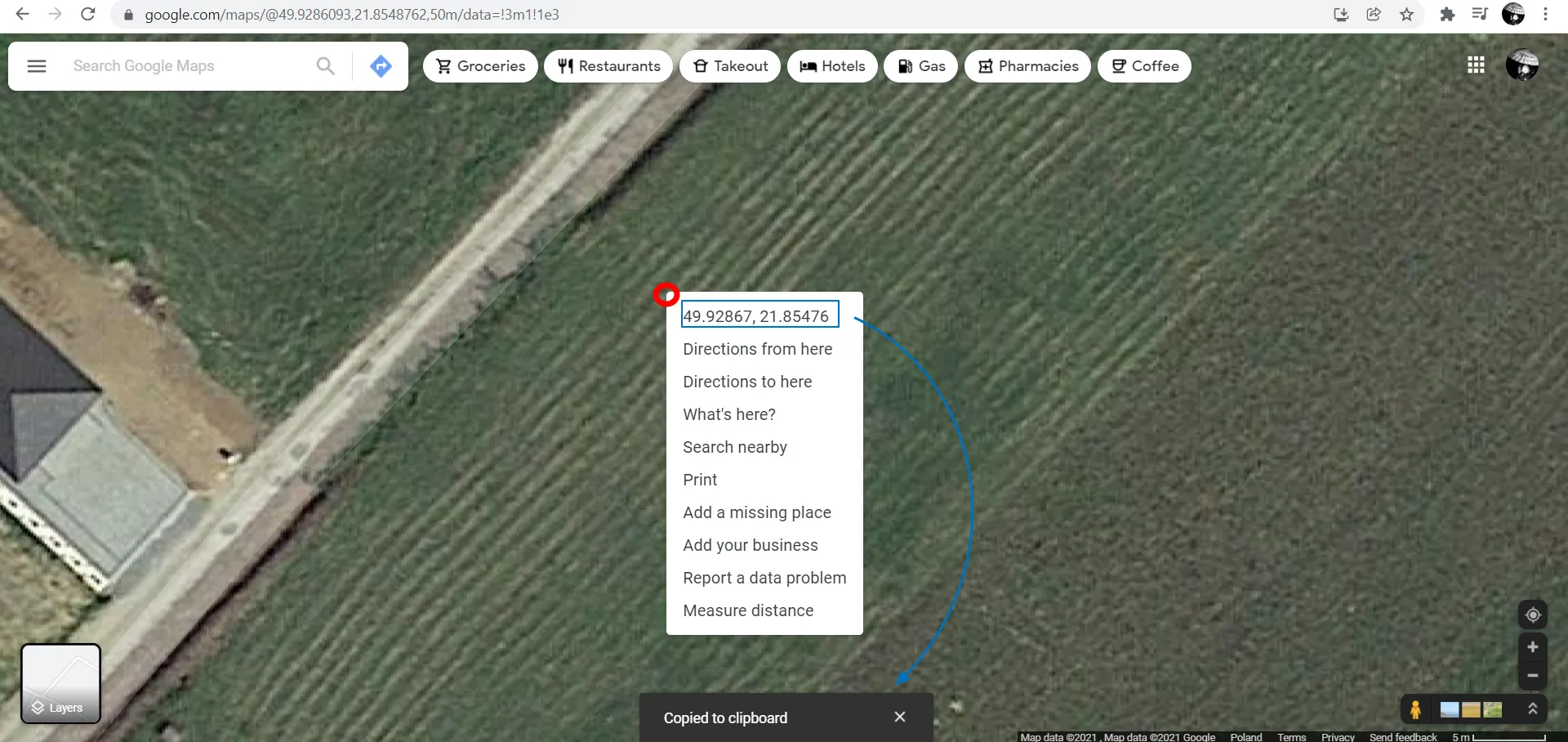
Pic. 16 Getting coordinates from Google Maps and copying them to the clipboard. Red point shows roughly where we have clicked the mouse. Blue bounded data is the coordinates data, which can be copied to the clipboard.
The most important thing to take a look at here is the red dot marked in the picture above. It shows roughly where we have clicked the mouse. If we decide to use the coordinates populated in the box (bounded blue), this point will become the center of the axes in Google Sketchup! Therefore sticking our object with the place where all the axes converge is really important.
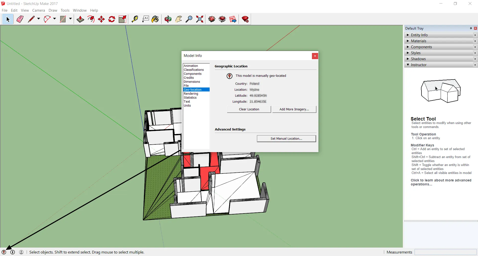
Pic. 17 Our model is manually geolocated in Google Sketchup.
When we finish the manual geolocation of our object, we should see the geolocation icon in the bottom bar turned red instead of black as previously.
9. Now, finally we can export our object as the .kmz file. We can select “File” from our main top bar and next “Export” -> “3D Model” -> “Save as type” -> .kmz.
10. The essence of our work is opening our Sweet Home 3D model in Google Earth (Pic. 18).
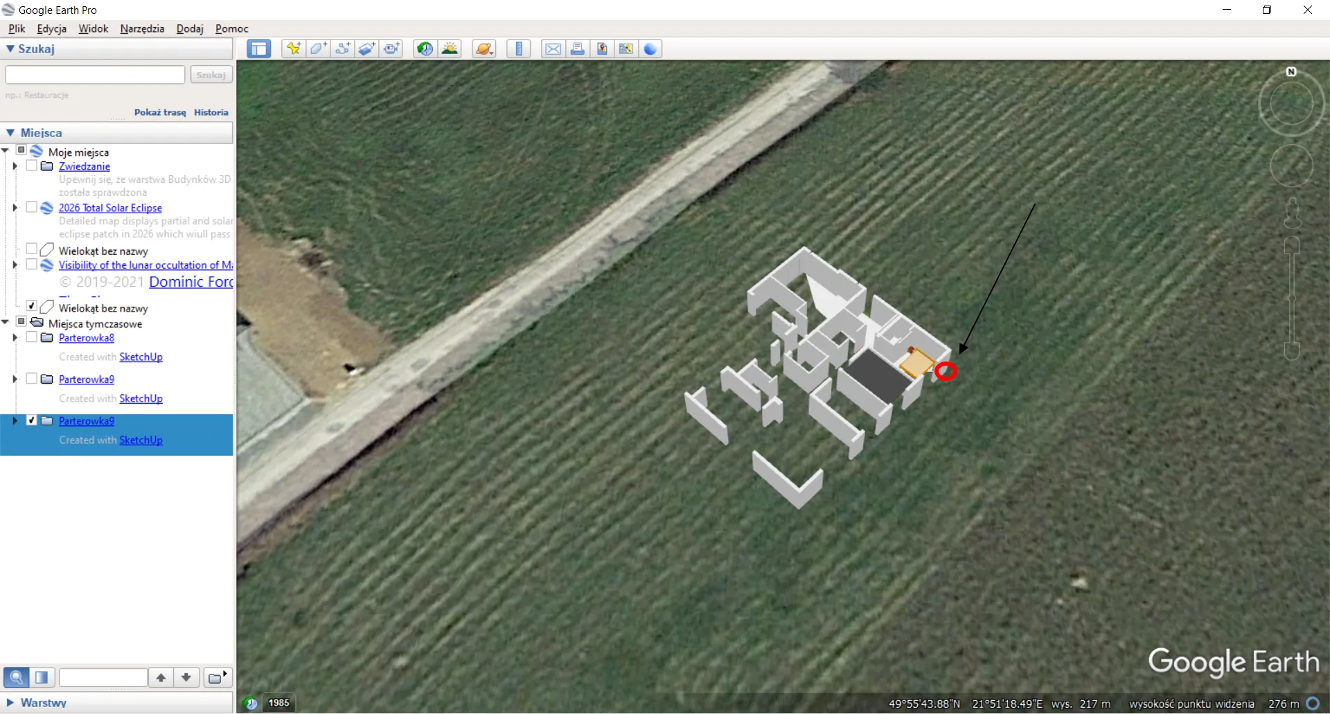
Pic. 18 Our Sweet Home 3D model in Google Earth.
However, there is one, very last thing to look at. Google Earth works on a slightly different basis than Sketchup does. The origin of the Cartesian system falls at an opposite corner of the building, as you can see above. It means, that some shifts might be required when you transfer the 3D model from Google Sketchup to Google Earth manually. Fixing is simple. You should measure the difference in distance between the place where your 3D object has been set and the place, where it should be. Afterward, you can use this distance to move your object in Google Sketchup and export it again.
ALTERNATIVE WAY OF GOOGLE SKETCHUP OBJECT MANUAL GEOLOCATION
According to the last sentence above, if you don’t want to move your object in Sketchup and export it again, you can always make these alterations within the .kmz file. First of all, you will need to extract the .kml component of this file in order to change some XML code inside. With the aim of it, you should be equipped with the 7Zip software, which can unzip your .kmz file properly.
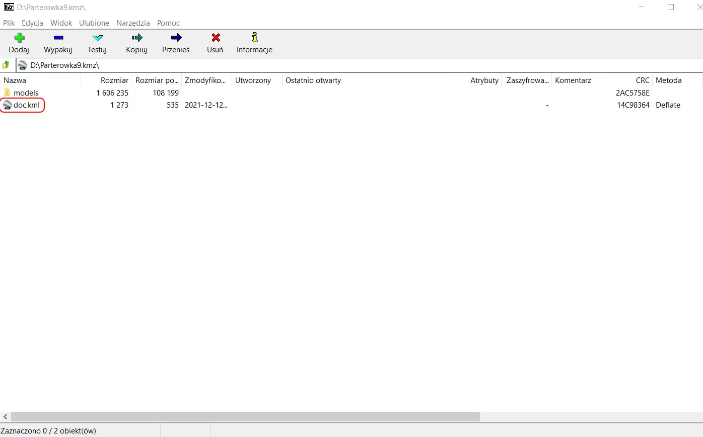
Pic. 19 Unzipping the .kmz file with our 3D model in 7Zip.
Next run for instance the Notepad ++ application, which can open the .kml file content and edit the values in the code shown below (Pic. 20).
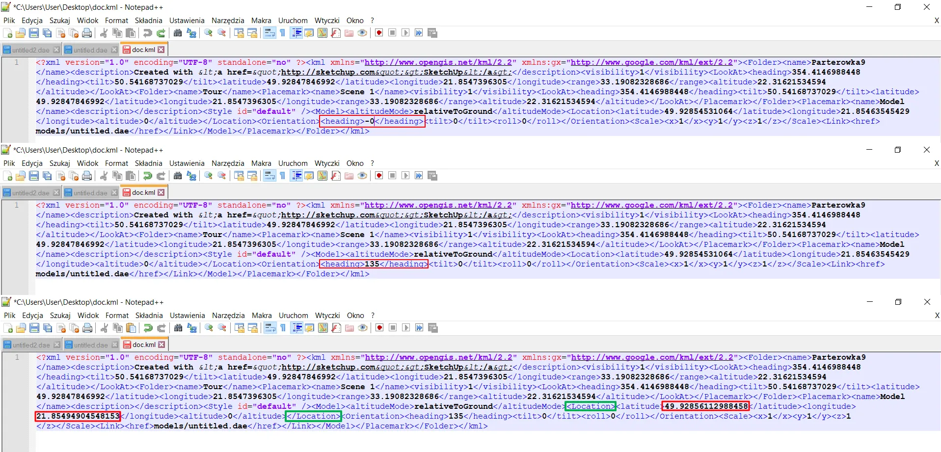
Pic. 20 Rotation and coordinates can be changed manually in Notepad ++ or other applications able to read the content of the .kml file.
Upload the extracted .kml file back to the .kmz directory when you are done. Finally, you should get the same effect. If at some point the building is placed some distance away from the desired place, you can just get the coordinates from Google Maps and paste them into the code shown above (Pic. 20).
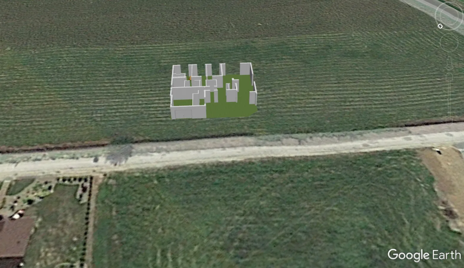
Pic. 21 Your Sweet Tome 3D model can look in Google Earth the same as mine.
Mariusz Krukar
Links:
- http://www.sweethome3d.com/
- Sweet Home 3D online
- Opensource.com: Interior design sweet home 3d
- Inches to centimeters converter
- AccuTrans 3D Software
- Sourceforge.net: Sweethome 3d – feature-requests/
- https://www.livehome3d.com/
- Help.sketchup.com: FAQ-add-location-changes-sketchup
- https://ladedu.com/how-to-use-the-snip-and-sketch-protractor-to-measure-angles/
- https://developers.google.com/kml/documentation/kmlreference#orientation
Forums:
- Viewing Sweet Home 3D model in Google Earth Pro
- Ways to get a better 3D view / Export to SketchUp and Google Earth
- Is there a way to enter building dimensions from a GPS device
- Export to Sketchup and Google Earth
- How to export from SweetHome3D to Sketchup for producing a cross section view
Wiki:
Youtube: